Safety first. The following information is for educational purposes. CNC machining involves high-speed rotating cutters. Always wear eye and ear protection, never leave a running machine unattended, and verify all feeds and speeds for your specific setup.
CNC 3D relief carving is two jobs pretending to be one: a roughing pass that hogs away waste fast, and a finishing pass with a ball-nose bit that walks the surface in tiny steps — 5–10% of its diameter — to leave the detail. Get the toolpath order, stepover, and workholding right and a hobby machine carves relief that looks impossible for the price. Get them wrong and you snap bits, burn hours, and sand out fuzz that should never have been there.
I run 3D relief work across the machines on my bench — the Shapeoko Pro is my daily driver with a 65mm VFD spindle, and the ball-screw Onefinity is what I reach for when a deep relief needs the gantry to stop flexing. This guide is the system I actually use at the controller: how the surface gets built up out of CAM operations, which bits earn their keep, how stepover trades finish for time, and where the job goes wrong long before the spindle ever spins. Every spoke below drills into one piece in depth.
What 3D Relief Carving Actually Is
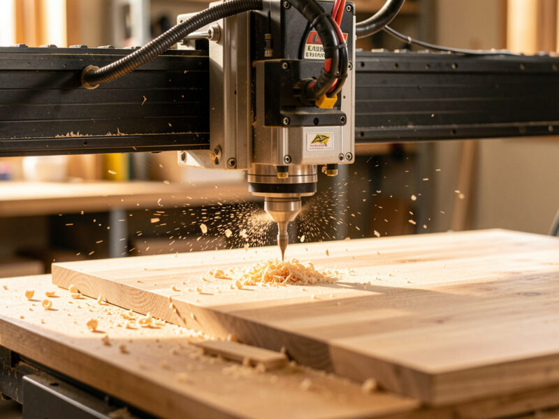
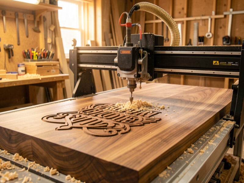
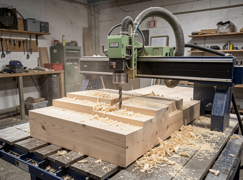
3D relief carving means cutting a continuously varying height field — a surface where the Z height changes everywhere, like a topographic map of a sculpture pressed into a panel. The machine reconstructs that surface by dragging a round-tipped bit across it in thousands of closely spaced passes. Unlike 2D profiling, there is no single depth; the Z axis is moving constantly.
This is the part new operators conflate and it matters for everything downstream. 2.5D work (pockets, profiles, the bread-and-butter of most CNC routing) cuts to flat depths with straight-walled bits. V-carving uses the angle of a V-bit to vary line width and create the look of hand-carved lettering and prismatic inlay — it is a clever 2D trick, not true 3D. If you want the difference spelled out, my guide to CNC engraving, V-carving, and inlays covers where the V-bit shines. True 3D relief is the only one of the three where a ball-nose bit traces a curved surface point by point, and that single fact drives the bits, the toolpaths, and the patience the job demands.
The model itself usually arrives as an STL, an STL-like mesh, or a greyscale heightmap (a depth map where white is high and black is low). Your CAM software wraps toolpaths around that surface. Whether the file came from a 3D sculpt, a downloaded model, or a photo turned into a heightmap, the machining problem is identical from there: rough it, then finish it.
The Two-Pass Reality: Rough First, Finish Second
Every relief carving worth keeping is at least two operations. The roughing pass removes the bulk of the material in stepped layers as fast as the machine can take it, leaving a rough terraced approximation of the surface. The finishing pass then skims that terraced surface with a small ball-nose bit at a tiny stepover to produce the smooth, detailed final form. Trying to do both in one pass is the single most common beginner mistake — it either takes forever or breaks the bit on the first deep plunge.
Roughing should use the biggest bit your detail allows and a 3D adaptive or pocket-clearing strategy that keeps the cutter loaded evenly. I lean on the same adaptive and trochoidal clearing logic I use for deep 2D pockets, because it keeps chipload constant and the spindle cool. Roughing leaves a “stock to leave” allowance — typically 0.3–0.5 mm — so the finish bit has a thin, even skin to remove instead of fighting full-depth steps.
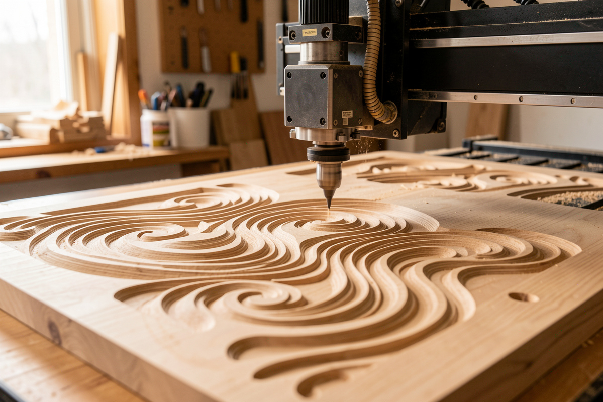
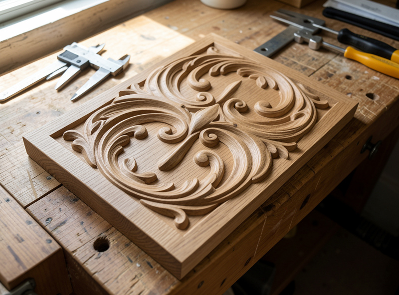
Finishing is where the detail lives, and it is slow on purpose. A small ball-nose at a 5–10% stepover walks back and forth (or around contours) building the surface out of overlapping arcs. This split — fast bulk removal then fine surfacing — is worth understanding in its own right; my deep dive on roughing vs finishing passes for 3D carving breaks down the allowances, stepdowns, and where people waste the most time.
Toolpath Strategies That Decide Your Finish
The finishing toolpath you choose changes the look of the surface as much as the bit does. There is no single best strategy — each one leaves the cutter marks running a different direction, and the right answer depends on the geometry. This is the core craft of relief work, and it is covered in full in my 3D carving toolpath strategies guide.
3D raster / parallel is the default: the bit sweeps in parallel lines like mowing a lawn. It is predictable and fast to compute, but on steep walls the lines spread out and finish gets coarse. 3D contour / Z-level follows constant-height rings and excels exactly where raster fails — steep sides — so the two are often paired (raster the shallows, contour the steeps). Pencil / corner finishing chases the valleys a larger bit could not reach, and flat finishing cleans truly horizontal areas. Pairing strategies by slope angle is how the pros get an even finish without a 12-hour single pass.
One thing the tutorials skip: the angle you raster matters. Running the parallel pass at 45° to the grain on a long flat face often hides scallops better than running it dead straight, because the eye reads diagonal tool marks as texture rather than as a defect.
The Bits: Ball-Nose Is the Star, Tapered Is the Workhorse
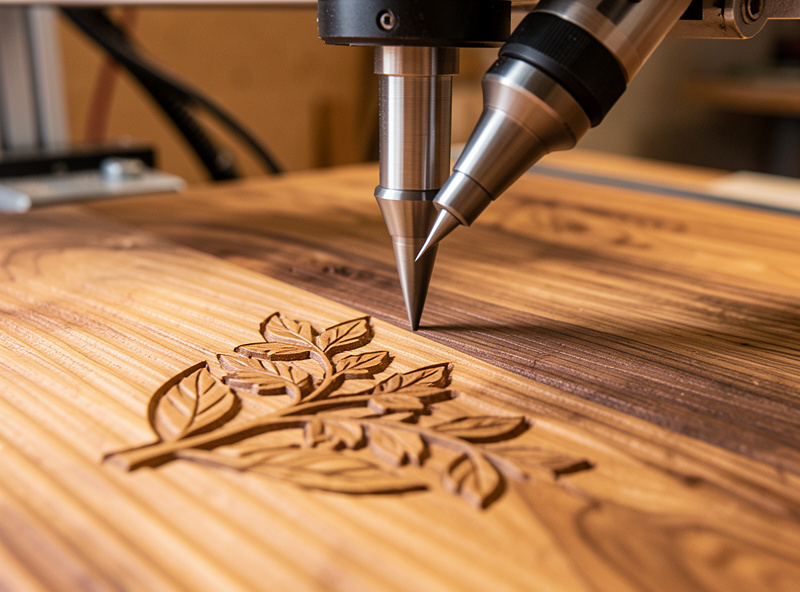
3D relief lives and dies on the ball-nose end mill. The round tip is what lets the cutter sit tangent to a curved surface at any angle without gouging — a flat-bottom bit physically cannot do this. For fine detail I run small ball-nose cutters down to 1/16″ and even 1/32″; for general finishing a 1/8″ ball is the everyday tool.
The catch is rigidity. A straight 1/32″ ball-nose on a long stick-out is a noodle — it deflects, chatters, and snaps. The fix the whole hobby world has converged on is the tapered ball-nose: a bit with a small ball tip but a conical, thickening shank behind it. You get the fine tip detail with vastly more stiffness, and on a flexy hobby gantry that difference is the whole ballgame. I keep a set of tapered ball-noses (typically with 1/32″ and 1/16″ tips) as my standard relief finishers. My full breakdown of which to buy is in the best 3D relief carving bits guide, and the geometry of the ball-nose itself — including why scallop height is set by tip radius — is in the ball-nose end mill for 3D carving deep dive.
For roughing, a 1/4″ or 1/8″ two-flute upcut or even a flat end mill moves material far faster than trying to rough with the ball-nose. Use the ball only for what it is for: the finish. If you are still building your tooling shelf, the broader CNC router bits guide and my tier-by-tier bit comparison cover the rest of the kit. As an Amazon Associate I earn from qualifying purchases. When I need to restock finishers I search for a tapered ball nose end mill set rather than guessing on a single size.
Stepover and Scallop Height: The Time-vs-Finish Trade
Stepover is the distance the bit shifts sideways between finishing passes, and it is the dial that controls everything you care about: surface smoothness, machining time, and how much sanding you face afterward. With a round-tipped bit, every pass leaves a tiny ridge — a scallop — between it and the next pass. Smaller stepover, smaller scallops, smoother surface, longer run. There is no free lunch.
The relationship is geometric, not linear, which is why dropping stepover from 10% to 5% does not just double the time — it can triple or quadruple it while the visible improvement shrinks. As a working rule I finish display pieces at 8–10% of bit diameter and drop to 5% only on faces that will be viewed up close in raking light. Below is how the trade actually plays out for a 1/8″ ball-nose.
| Stepover (% of dia) | Stepover (1/8″ ball) | Relative finish | Relative time | Best for |
|---|---|---|---|---|
| 15% | ~0.48 mm | Visible ridges, needs sanding | 1x (fastest) | Backs, hidden faces, test cuts |
| 10% | ~0.32 mm | Good, light sanding | ~1.5x | Most decorative relief |
| 8% | ~0.25 mm | Very good | ~2x | Display faces, hardwood |
| 5% | ~0.16 mm | Near sand-ready | ~3x | Fine detail, raking-light pieces |
| 3% | ~0.10 mm | Mirror-class, rarely worth it | ~5x+ | Tiny jewelry-scale work |
The other half of finish quality is the bit tip radius. A larger ball leaves smaller scallops at the same stepover but loses fine detail; a smaller ball captures detail but scallops faster. Matching tip size and stepover to the smallest detail in your model — not to the whole panel — is the skill. The math behind scallop height lives in the ball-nose end mill spoke.
Choosing Material: Wood First, but Not All Wood
Material choice decides how much detail survives the cut. Tight, even-grained hardwoods hold crisp relief; open-pored or wildly figured woods tear out fine detail no matter how slow you go. My go-to relief woods are hard maple and cherry — tight grain, predictable, they take detail cleanly and finish without drama. Basswood and tupelo are the carver’s classics for a reason: soft, almost grainless, forgiving on tiny ball-noses. Walnut carves beautifully but its open pores can fuzz the finest lines.
What to avoid for fine relief: ring-porous woods like red oak (the pore lines fight your detail), anything with reversing or interlocked grain, and most softwoods like pine where the soft earlywood crushes under a small bit instead of cutting. MDF carves detail shockingly well and is a great proofing material, but it drinks finish and the dust is nasty. The full ranking — including the specific feeds I run for each — is in my best wood types for 3D CNC carving guide, and general hardwood settings live in cutting hardwood.
Workholding for Long Relief Jobs
It is always workholding. A relief finish pass can run for hours, and if the part shifts even slightly partway through, the whole surface registers the move as a visible step you cannot sand out. The hold has to survive the entire job, not just the first 20 minutes.
For panel relief I default to a flat, surfaced spoilboard with the blank screwed down through the waste margin, or cam clamps on a T-track wasteboard. For thinner stock where screws would show, I reach for the vacuum table — it ended most of my “the part lifted” stories. Crucially, relief models are usually carved into a blank thicker than the deepest cut, so you keep clamps and screws in the untouched margin around the carving and machine only the interior. The full method set is in my workholding guide. One more thing the videos skip: surface your spoilboard flat before a big relief, because if the bed is not coplanar with the gantry, a “flat” background in your model comes out as a visible wedge.
CAM Software for Relief Carving
3D relief is where CAM packages separate. For sign-shop relief and decorative panels, VCarve Pro is the hobby standard — it imports models and component greyscales, generates clean roughing and finishing toolpaths, and previews the result so you catch problems before you cut. I walk through the exact workflow in my VCarve Pro 3D carving tutorial, and my long-term take is in the VCarve Desktop review.
For models you sculpt or modify yourself, Fusion 360 has serious 3D machining strategies (adaptive roughing, parallel, scallop, contour, pencil) on its free hobby tier — see my Fusion 360 for hobby CNC setup. Carbide Create Pro adds 3D to the free Carbide Create. Whichever you pick, the operation logic in my CAM toolpath mastery guide carries over, and the broader CAM software comparison helps you choose. The one rule that holds across all of them: always run the 3D toolpath simulation before you cut, because a bad finishing path wastes hours, not minutes.
Dialing Feeds and Speeds for Relief Finishing
Relief finishing breaks the normal feeds-and-speeds instinct. Because the ball-nose is taking a whisker-thin pass at a tiny stepover, the limiting factor is rarely chip load — it is rigidity and finish. A small ball-nose at full chipload feed will deflect and chatter; the trick is keeping the spindle RPM up and the feed moderate so the effective chip stays sane and the tip does not rub. Rubbing instead of cutting work-hardens the surface on aluminum and burnishes/burns wood.
My starting point for a 1/8″ ball in hardwood is a high spindle RPM with a feed that keeps a real (if small) chipload, then I let the surface tell me whether to push feed up or back it off. The chipload-first reasoning that makes this repeatable is in my chipload calculation and feeds and speeds mastery guides — both apply directly here, with the caveat that 3D finishing leans toward “finish and rigidity” over “material removal rate.” And do not skip dust collection: in a finish pass, a recut chip is a divot in your surface, so chip evacuation is a finish-quality issue, not just a lung one.
Putting It Together: A Relief Job, Start to Finish
Here is the whole sequence as I run it. Pick a tight-grained blank thicker than your deepest cut. Surface the spoilboard, clamp the blank in the untouched margin. In CAM: import the model, set the machining region, generate a 3D adaptive roughing pass with a 1/4″ or 1/8″ end mill leaving 0.4 mm stock. Add a finishing pass with a tapered ball-nose at 8% stepover, pairing raster for shallow areas with Z-level contour for steep walls. Simulate. Zero the machine, run roughing, swap to the ball-nose and re-zero Z carefully (a 0.1 mm Z error shows in the finish), run finishing. Light sanding, finish of choice. That is it — the magic is entirely in the prep, not the cutting.
The Mistakes That Ruin Relief Carvings
After enough hours at the controller you learn that relief failures repeat. The first is re-zeroing Z badly after the bit change: rough and finish must share the same Z origin, and a 0.1 mm error shows as a uniform skin left behind or a surface cut too deep. Use a touch plate and re-zero Z deliberately — my touch probe and touch plate guide covers doing it repeatably.
The second is climb-milling fine detail on a flexy setup. On a hobby gantry, an aggressive climb pass into a thin standing detail can grab and snap the standing feature or the bit; for delicate relief I keep the finishing feed moderate and let the small effective chip stay controlled. The direction reasoning is the same one I lay out for general routing — climb gives a cleaner wall when the machine is rigid enough to hold it, and conventional is the safer fallback on a noodly bit at long stick-out.
The third is skipping the simulation. A 3D finishing toolpath that looks fine in the parameter dialog can rapid the bit straight through a standing detail on a retract move. I have watched a path try to plunge full-depth because the stock height was set wrong — the simulation is the only thing that catches it before the spindle does. The fourth is fuzz: tearout and whiskering that look like a bad bit but are usually a dull tip, a recut chip, or the wrong species. A fresh tapered ball-nose, good chip evacuation, and a tighter-grained wood fix nearly all of it.
Explore the Cluster
Each part of the workflow above has its own detailed guide:
- Best 3D relief carving bits for CNC — tapered ball-nose, tip sizes, and what to actually buy.
- Ball-nose end mill for 3D carving — geometry, scallop math, and stepover.
- VCarve Pro 3D carving tutorial — step-by-step from model to G-code.
- Best wood types for 3D CNC carving — which species hold detail and which fight you.
- Roughing vs finishing pass — allowances, stepdowns, and time savings.
- 3D carving toolpath strategies — raster, contour, pencil, and pairing them by slope.
Frequently Asked Questions
Can a hobby CNC really do 3D relief carving?
Yes. Any GRBL desktop CNC with a router or spindle can carve 3D relief — the bit just traces a curved surface in many small passes. Rigidity affects how fast and how fine you can go, but even an entry machine carves clean relief in basswood or maple with a tapered ball-nose and an 8 percent stepover.
What bit do I need for 3D relief carving?
A ball-nose end mill for finishing, ideally a tapered ball-nose for rigidity, plus a flat or upcut end mill for roughing. A 1/8 inch ball handles general finishing; drop to a 1/16 or 1/32 inch tapered ball for fine detail. The round tip is what lets it follow a curved surface without gouging.
Why does my 3D carving take so many hours?
Finishing passes use a tiny stepover, so the bit makes thousands of closely spaced passes. Halving stepover from 10 to 5 percent can triple the time. Rough fast with a big bit, finish only as fine as the piece actually needs, and reserve 5 percent stepover for faces viewed up close.
What is stepover in 3D carving?
Stepover is how far the ball-nose shifts sideways between finishing passes. Smaller stepover leaves smaller ridges (scallops) and a smoother surface but takes much longer. A practical default is 8 to 10 percent of bit diameter for decorative relief, dropping to 5 percent for fine display work.
Do I need two separate passes for relief carving?
Almost always. A roughing pass clears bulk material fast with a larger bit, leaving about 0.3 to 0.5 mm of stock. A finishing pass then skims that with a small ball-nose for detail. Combining them into one pass either breaks the bit on deep plunges or runs absurdly long.
What wood is best for 3D CNC relief carving?
Tight, even-grained woods hold detail best: hard maple, cherry, basswood, and tupelo. Avoid ring-porous woods like red oak and soft, uneven softwoods like pine for fine detail. MDF carves detail well and is great for proofing but soaks up finish and produces nasty dust.
Which software do I use for 3D relief carving?
VCarve Pro is the hobby standard for decorative and sign relief; Fusion 360 covers self-sculpted models with full 3D strategies on its free tier; Carbide Create Pro adds 3D to Carbide Create. All generate roughing and finishing toolpaths. Always run the 3D simulation before cutting.
Related Articles
- 3D CNC Roughing and Finishing Toolpaths Explained
- V-Carve Toolpaths Tutorial: Letters, Inlays, and Prismatic Carving
- Ball Nose End Mill: 3D Contouring and Finishing
- CNC Cutting Hardwood: Oak, Maple, Walnut Settings
- CNC Router Sign Making: The Complete Guide
- Troubleshooting Desktop CNC: Chatter, Lost Steps, Broken Bits