Safety first. The following information is for educational purposes. CNC machining involves high-speed rotating cutters. Always wear eye and ear protection, never leave a running machine unattended, and verify all feeds and speeds for your specific setup.
Setting zero is the single step that decides whether a job comes off the machine right or scrapped, and it’s also the step most people fudge with a scrap of paper. A CNC touch probe takes the guesswork out of it: instead of eyeballing where the tool kisses the stock, you let the controller find the surface electrically and set the work offset to a real, repeatable number. Across the machines I run, going from paper-feeler zeroing to a proper touch plate and a sprung 3D probe is the upgrade that quietly killed an entire category of ruined parts — the two-sided jobs that didn’t line up, the tool changes that gouged, the engravings that ran a hair deep on one side of the board.
This is the deep dive on the two tools that get conflated and shouldn’t be: a simple conductive Z touch plate of known thickness, and a sprung 3D touch probe that finds edges, corners, and bore centers. They solve different problems, they cost wildly different amounts, and knowing which one you actually need saves both money and a lot of confusion. If you want the broader setup picture first, the complete CNC workflow guide walks the whole job from CAD to finished part, and zeroing is the hinge it all turns on.
A quick note: some links below are affiliate links. Buy through one and I may earn a small commission at no extra cost to you. I only point to gear I’d actually clamp to my own bench and zero a part with — details on my disclaimer page.
Why Paper and Feeler-Gauge Zeroing Falls Apart
The classic method is to jog the tool down onto the stock with a slip of paper or a feeler gauge underneath, lowering until the paper just drags, then setting Z zero and accounting for the paper’s thickness. It works, sort of, for a single-side job where absolute accuracy doesn’t matter much. The trouble is it depends entirely on your hand and your eye, and it’s nowhere near repeatable. Two people drag the paper to “just grabbing” at two different points; the same person does it differently on a tired Friday than a fresh Monday. You’re guessing to maybe a few thousandths on a good day, and on a bad one you’re off by a tenth of a millimeter without knowing it.
That slop is invisible right up until it isn’t. The moment it bites is two-sided work, where you machine the front, flip the stock, and re-zero to cut the back. If your two zeroes don’t agree, the features on the back don’t line up with the features on the front — and there’s no fixing it after the fact. The other moment is tool changes mid-job: pull the 1/4-inch roughing bit, drop in a ball-nose for finishing, and the new tool sits at a different length in the collet. Re-zero by eye and you’ve just introduced a step in your surface. A touch plate makes both of these a button-press instead of a prayer, because the controller finds the surface the same way every single time.
The Conductive Z Touch Plate: Known Thickness, Honest Zero
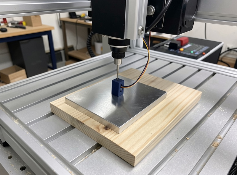
The simplest tool here is a conductive Z touch plate — a flat metal block of precisely known thickness with two wires. One clips to the bit (or the collet), the other connects to the plate. You set the plate on top of your stock, run the controller’s probe macro, and the spindle lowers slowly until the bit touches the plate and completes the circuit. The instant continuity is detected, the machine stops, reads its position, subtracts the known plate thickness, and sets Z zero to the true top of the stock. No paper, no feel, no guessing — the plate is the same thickness every time, so the zero is repeatable to the thousandth.
This is the highest-value, lowest-cost upgrade on the bench, and it’s where almost everyone should start. A basic CNC touch plate Z probe costs little and pays for itself the first time it saves a finish pass from running deep. The macro it relies on is built into GRBL senders like Carbide Motion, gSender, and UGS, and into the firmware on most hobby machines, so on a Shapeoko, Onefinity, or Genmitsu it’s largely plug-and-go. The one thing to get right is telling the sender the exact plate thickness — that number is the whole accuracy of the system.
The Conductive-Plate Catch Nobody Mentions Up Front
Here’s the limitation that trips up new owners: a conductive touch plate works by completing an electrical circuit between the tool and the plate, which means it needs both a conductive tool and a conductive path. A carbide bit is conductive, and a metal plate is conductive — but wood, MDF, acrylic, and plastic are not. When the plate sits on top of insulating stock, the circuit only closes through the bit-to-plate contact, which is fine for Z because the plate is the thing being touched. The problem is the magnet or clip half of the system. Most plates rely on a small magnet clip that grounds the workpiece, and on non-conductive material there’s nothing for that clip to grab electrically.
In practice this means Z probing on wood works as long as you clip the ground lead directly to the bit or collet rather than expecting it to ground through the stock. If you try to use a plate that grounds through the workpiece on a sheet of acrylic, the circuit never completes and the spindle just keeps driving down into the plate — a fast way to bend a plate or snap a bit. The fix is simple once you know it: clip the magnet to the tool shank or collet nut, not the wood. For XY edge-finding with a conductive plate, though, you genuinely do need a conductive workpiece, which is why edge-finding on wood pushes you toward a different tool entirely. This is exactly the kind of gotcha I cover in the desktop CNC troubleshooting guide — the failure looks like a broken probe but it’s a circuit you never closed.
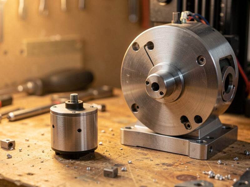
The Sprung 3D Touch Probe: Finding Edges, Corners, and Centers
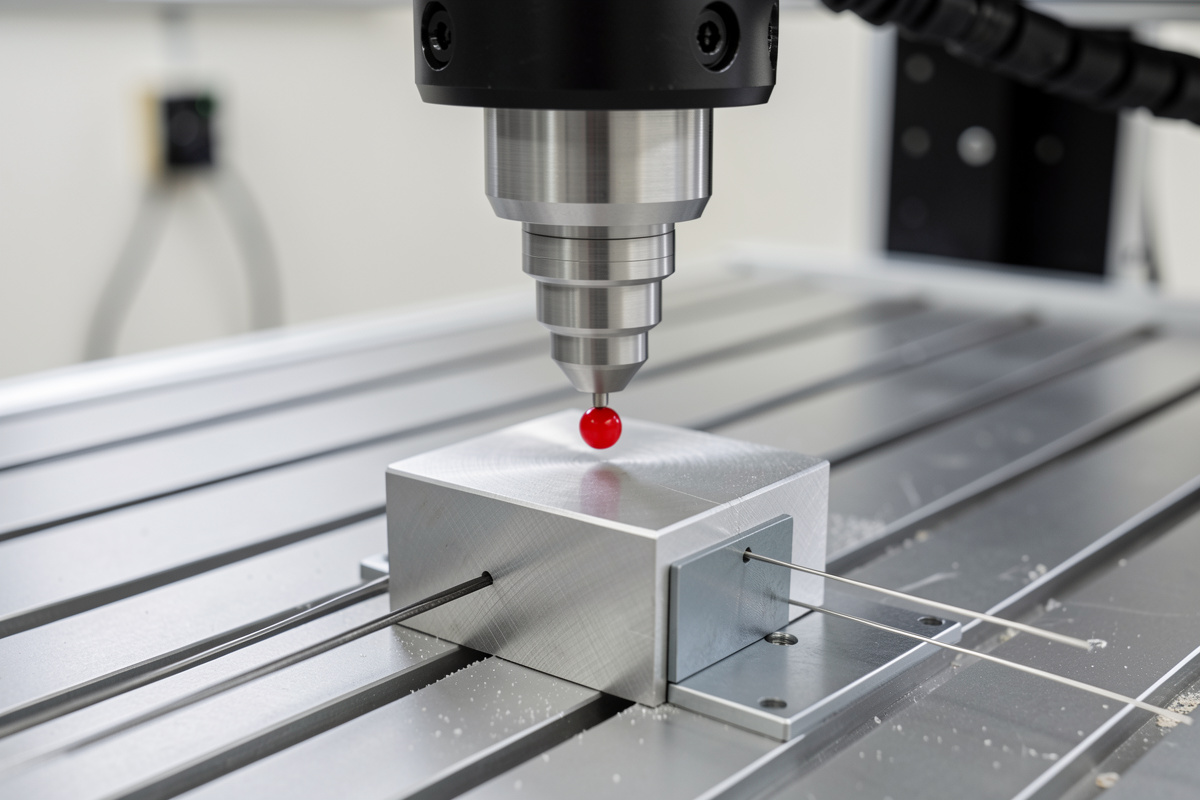
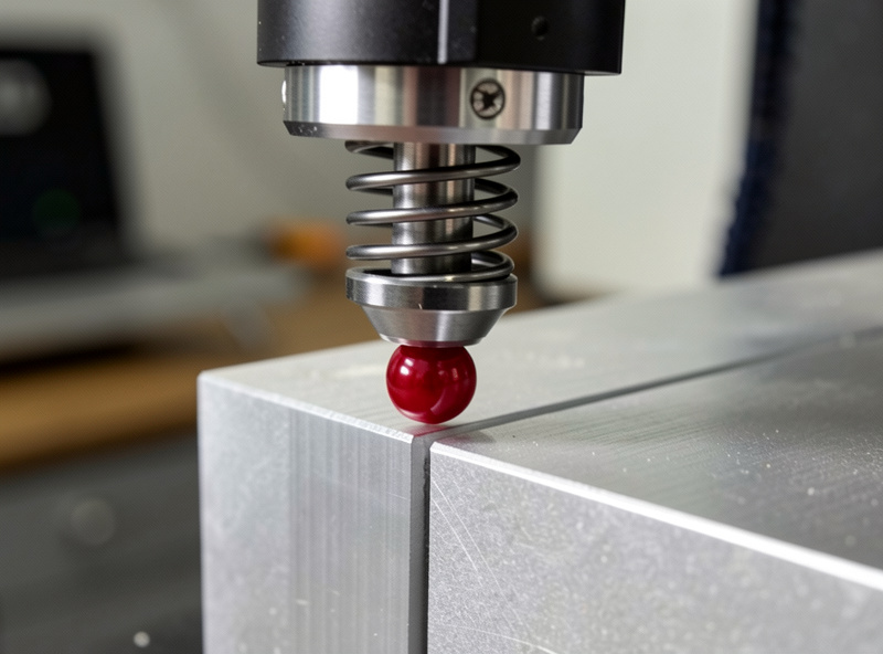
A 3D touch probe is a different animal. Instead of a flat plate, it’s a precision instrument with a sprung, deflectable stylus tipped with a hardened ball. You chuck it in the spindle exactly like a tool, and when the ball contacts a surface from any direction — top, side, or angle — the stylus deflects and triggers the signal. Because it triggers on contact from any direction, it can find far more than a plate ever could: the top surface for Z, an edge for X or Y, a full corner to set XYZ in one routine, and even the center of a bore or boss by probing opposite walls and splitting the difference.
This is what unlocks true XYZ corner finding. With a touch plate you set Z and then square the stock to the machine by hand or against a fence to get X and Y. With a 3D probe you drop it near a corner, run the corner macro, and the machine probes the top, then one side, then the adjacent side, and sets all three axes to that corner automatically — repeatably, to a couple of thousandths or better. For two-sided work and for jobs where the stock has to register to a known datum, that repeatability is the whole game. A quality CNC 3D touch probe is the upgrade that makes flip jobs and precise fixturing genuinely trustworthy rather than hopeful. The trade is cost and a bit of macro setup, and the stylus is delicate — a crash into a sprung probe is an expensive lesson, so I always probe at a slow feed with a sane retract.
How the Probe Macro Actually Works
Whether it’s a plate or a 3D probe, the magic is the macro — a short G-code routine the sender runs when you hit “probe.” For a Z plate the routine is straightforward: select probe mode, feed the spindle down slowly using a G38.2 straight-probe move that halts the instant continuity triggers, record the machine position at trigger, then offset by the plate thickness and write the work zero. The sender handles the math; you just place the plate and click. The slow feed matters — probe too fast and the spindle overshoots before the controller reacts, which both hurts accuracy and risks driving the tool into the plate.
For a 3D probe the same G38.2 logic runs in sequence across axes. A corner routine touches Z first to establish the top, retracts, then moves to probe one face for X, retracts, probes the adjacent face for Y, and combines the three triggers into a corner datum. Bore-centering probes one wall, crosses to the opposite wall, and sets the center as the midpoint, then repeats on the perpendicular axis. None of this requires writing G-code by hand — gSender, UGS, and the Carbide stack ship corner and center macros — but understanding that it’s just a sequence of slow straight-probe moves with retracts demystifies what’s happening and makes troubleshooting a stalled probe far less mysterious. If you’re hand-editing posts or building custom routines, the Fusion 360 for hobby CNC guide covers where probing fits into a CAM-driven workflow.
Tool-Length Offsets and Why Tool Changes Stop Being Scary
The place a touch plate quietly earns its keep most often is the manual tool change mid-job. Rough a pocket with a 1/4-inch endmill, then swap to a ball-nose to finish the 3D surface — the new bit almost never sits at the same length in the collet as the old one. Re-zero by eye and you’ve shifted Z by however much your hand was off, leaving a visible step where the roughing depth and finishing depth disagree. With a plate, the tool-change routine is mechanical: pause, swap the bit, jog over the plate, hit probe, and the controller re-establishes Z to the same true surface for the new tool. The work zero stays honest across every tool in the job.
This is the same principle that lets you set a tool-length offset and trust it. Probe each tool against the same reference and the controller knows exactly how far each one sticks out, so a multi-tool job comes off the machine as one continuous surface instead of a terraced mess. It’s the difference between a finish job that needs sanding to hide a step and one that comes off clean. The discipline of probing every tool change is also what makes accessory templating jobs like my CNC spot-drill templates and weld fixtures repeatable — the holes land where the drawing says because every tool referenced the same zero.
The XYZ Zero Corner Block: A Middle Path
Between the cheap Z plate and the pricey 3D probe sits the XYZ zero corner block — a stepped conductive block you set against a corner of the stock so the controller can probe Z, X, and Y off its three known reference faces in one routine. It’s still a conductive-contact tool, so it carries the same conductive-workpiece caveat for the XY faces, but it gives you corner-finding capability at a fraction of a 3D probe’s cost. For metal work and for anyone who needs repeatable XYZ origin without the 3D-probe budget, a solid CNC XYZ zero corner block is the sensible middle rung. On aluminum and other conductive stock it’s genuinely excellent; on wood it’s back to Z-only unless you add a conductive reference.
I think of these three as a ladder, not competitors. Most people should own the Z plate from day one, add the corner block when conductive-stock XYZ origin starts to matter, and step up to the sprung 3D probe only when non-conductive edge-finding, bore-centering, or genuine sub-few-thou repeatability across flip jobs becomes the bottleneck. Here’s how they actually compare.
Z Plate vs XYZ Corner Block vs 3D Probe
| Tool | What it finds | Relative cost | Repeatability | Works on non-conductive stock? |
|---|---|---|---|---|
| Conductive Z touch plate | Z (top of stock) only | Lowest | To the thousandth | Z yes (ground to bit); XY no |
| XYZ zero corner block | X, Y, and Z off one corner | Medium | To the thousandth on conductive stock | Z yes; XY needs conductive work |
| Sprung 3D touch probe | Z, edges, full corners, bore/boss centers | Highest | A couple thousandths or better, any direction | Yes — mechanical trigger, no circuit needed |
Getting Repeatable Zeros in Practice
A few habits make any of these tools reliable. Always probe at a slow feed — the controller needs time to react to the trigger, and a fast probe overshoots. Tell the sender the exact plate or stylus dimensions; a wrong number is a wrong zero, cleanly and confidently. Keep the contact surfaces clean, because a chip or a film of cutting fluid between bit and plate adds thickness you didn’t account for. And verify the first zero on an unfamiliar setup: probe, then jog the tool to touch the surface manually and confirm the displayed Z reads close to zero before you trust it on a real cut.
For conductive probing specifically, confirm continuity before you commit — most senders show a probe-pin status, and touching the bit to the plate should flip it. If it doesn’t, you’ve got a wiring or grounding problem, not a machine problem, and finding that out before the macro runs beats finding it out as the spindle drives through the plate. Dialing zero in this carefully is the same discipline that makes a feeds and speeds setup repeatable — accuracy compounds when every part of the job references the same honest numbers, and the dial indicator and edge finder on my bench are the manual backstop I check a new probe against.
Frequently Asked Questions
What is a CNC touch probe and what does it do?
A CNC touch probe sets work zero electrically instead of by eye. A simple conductive Z touch plate of known thickness finds the top of the stock, while a sprung 3D probe finds edges, corners, and bore centers from any direction. Both let the controller set zero the same way every time, repeatable to the thousandth.
Why is paper or feeler-gauge zeroing not good enough?
Paper zeroing depends on your hand and eye, so it is not repeatable. It fails most on two-sided work, where the front and back features will not line up if the two zeroes disagree, and on tool changes, where a new bit sits at a different length and re-zeroing by feel leaves a step in the surface.
Does a conductive touch plate work on wood and plastic?
For Z, yes, as long as you clip the ground lead to the bit or collet rather than expecting it to ground through the stock. Wood, MDF, and acrylic are not conductive, so a plate that grounds through the workpiece will not complete the circuit. XY edge-finding with a conductive plate genuinely needs conductive material.
What is the difference between a touch plate and a 3D touch probe?
A touch plate is a flat conductive block that finds Z only and needs a conductive contact path. A 3D probe is a sprung stylus that triggers on contact from any direction, so it finds Z, edges, full XYZ corners, and bore centers mechanically, and it works on non-conductive stock because it needs no electrical circuit.
How does probing help with tool changes?
When you swap bits mid-job, the new tool almost never sits at the same length in the collet. Probing the new tool against the same plate re-establishes Z to the true surface, so a multi-tool job comes off as one continuous surface instead of a terraced step where roughing and finishing depths disagree.