Safety first. The following information is for educational purposes. CNC machining involves high-speed rotating cutters. Always wear eye and ear protection, never leave a running machine unattended, and verify all feeds and speeds for your specific setup.
CNC feeds and speeds mastery comes down to one number you control indirectly: chipload, the thickness of the chip each flute carves. Get chipload right and the bit clears heat in the chip instead of soaking it; feed, RPM, and depth of cut are just the dials you turn to land it. The manufacturer chart is a starting point, not a recipe.
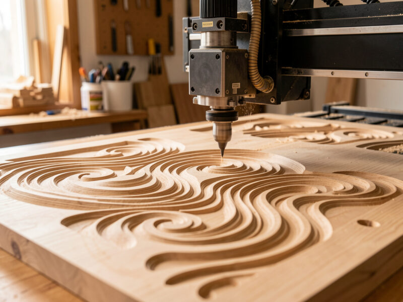
I run a Shapeoko Pro with a 65mm 1.5kW air-cooled VFD spindle as my daily driver, with an Onefinity Woodworker, a couple of Genmitsu machines, and a steel-frame build on the same bench for comparison. Across those machines the cuts that finish clean all trace back to the same handful of decisions. This guide is the system I use to make them — the reasoning behind every feed in my logs, with deep-dive links to the material- and toolpath-specific guides where the actual numbers live.
The Four Numbers That Decide Every Cut
Every feeds-and-speeds decision is four numbers turning against each other: spindle RPM, feed rate (how fast the machine moves the cutter through the work), depth of cut (DOC, how deep the flute bites), and stepover (how much of the cutter’s width engages on each pass). Change one and you have changed the load on the bit, the machine, and your workholding.
The trap is treating those four as the inputs. They are not — they are the outputs. The real input is chipload, and once you think chipload-first, the four numbers stop being a guessing game and become arithmetic. Feed rate equals RPM multiplied by chipload multiplied by the number of flutes. That single relationship is the spine of everything below, and it is why I dropped the habit of copying a chart row and hoping.
Chipload First: Why I Stopped Reading the Manufacturer Chart Straight
Chipload is the thickness of material each flute removes per revolution, and it is the only feeds-and-speeds variable that maps directly to whether a bit survives. Too thin and the flute rubs instead of cuts — friction, heat, a dull edge, and in metal, work hardening. Too thick and you overload the flute and snap it. The sweet spot is a window, not a point, and every bit maker publishes a version of it.
So why ignore the chart? Because the chart assumes a rigid machine feeding as fast as the chipload demands. On a hobby gantry you often cannot feed that fast, which quietly drags your real chipload below the window and starts the rubbing-and-burning cycle. The fix is counterintuitive and it is the single most useful thing I have learned at the controller: when you cannot raise the feed, lower the RPM. I walk the full method in the chipload calculation guide, and the chart itself still earns a place on my wall as a sanity check — see the CNC feeds and speeds chart and the spindle RPM by material breakdown for the lookup numbers.
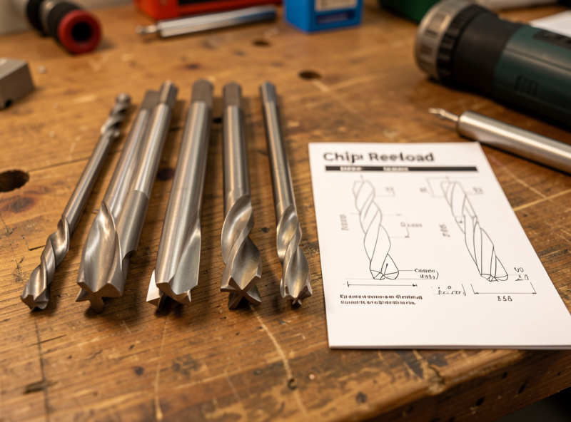
Flute count is part of the same equation. A single-flute O-flute clears one big chip per revolution — ideal for plastics and soft material where chip evacuation and heat are the whole game. A two-flute doubles the feed for the same chipload but halves the room each chip has to escape. I keep end mills in 1/8″ and 1/4″ single-flute, two-flute up and downcut, and compression, and I choose by the cut, not by habit. The tooling fundamentals guide covers how flute geometry changes the math.
The Rigidity Tax Nobody Charts
Here is what the unboxing videos skip: a hobby CNC charges a rigidity tax on every aggressive cut, and you pay it in deflection, chatter, and broken bits. The cutter wants to be fed at its ideal chipload; the gantry wants to flex away from the load. The lighter and more belt-driven the machine, the bigger the tax. My Onefinity’s ball screws hold a heavier cut than my belt-driven machines will, and a steel-frame build holds more again — same bit, same material, different ceiling.
This is why “what feed should I use” has no single answer. The honest version is: start at the chipload your bit wants, then back the depth of cut and feed off until the machine stops complaining — the cut goes quiet, the finish cleans up, and the chips look like chips instead of dust. A rigid machine lets you run nearer the bit’s limit; a flexy one makes you trade depth for passes. Counting that tax is the difference between a feed that works on a video and a feed that works on your spoilboard. It is also why the cheapest machine is rarely the cheapest total cost once you tally broken bits and re-cuts — a theme I dig into across the spindle and motion guide.
A Working Feeds-and-Speeds Reference
These are starting chiploads I dial from for a 1/4″ cutter on a reasonably rigid hobby machine, then verify by reading the cut. Treat them as the center of a window, scale chipload down for a 1/8″ bit, and always confirm against your bit maker’s range. Aluminum and copper especially reward starting conservative and working up.
| Material | Tool I reach for | Chipload (1/4″, in/tooth) | Spindle RPM | What bites you |
|---|---|---|---|---|
| Softwood (pine, cedar) | 2-flute upcut | 0.005–0.011 | 16,000–18,000 | Fuzzing; keep the feed up |
| Hardwood (oak, maple, walnut) | Compression or 2-flute | 0.005–0.009 | 14,000–18,000 | Maple burns if you dwell |
| Plywood / MDF | Compression / downcut | 0.004–0.009 | 15,000–18,000 | Abrasive; dulls bits fast |
| Acrylic / polycarbonate | Single-flute O-flute | 0.003–0.007 | 12,000–16,000 | Melts and re-welds |
| HDPE / Delrin | Single-flute O-flute | 0.006–0.012 | 12,000–16,000 | Stringy if RPM too high |
| Brass (C360) | 2-flute | 0.002–0.004 | 10,000–15,000 | Grabby; near-zero rake helps |
| Copper | Single-flute, sharp | 0.0015–0.003 | 9,000–13,000 | Gummy; smears on a dull edge |
| 6061 aluminum | Single/2-flute + air or mist | 0.001–0.003 | 10,000–18,000 | Chip welding; never recut chips |
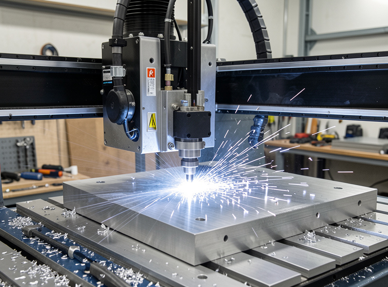
Notice the metals sit far lower than the wood. That is not timidity — it is chip-thinning and heat. A thin aluminum chip carries heat away if it is the right thickness and gets blown clear; let it go thin and recut and you get chip welding, a galled edge, and a snapped cutter. The aluminum feeds and speeds guide carries the full aluminum recipe.
Reading the Cut: Chips, Sound, and Finish
The chart gets you into the ballpark. Your senses get you to the right seat. I judge a cut three ways before I trust the numbers, and all three are faster than re-running the math.
First, the chips. I want chips, not dust. Dust means the chipload is too low and the bit is rubbing — it is cooking itself and the work. Long stringy chips in plastic mean the RPM is too high or the feed too low. Discolored blue chips in metal mean heat is going into the chip instead of away, which is the wrong direction. Second, the sound. A dialed cut has a steady, even tone; chatter is a rattling buzz that tells you the machine is deflecting and you need less depth, less stepover, or a shorter stick-out. Third, the finish and the edge. Burn marks in maple, melted slag in acrylic, a fuzzy edge in pine — each points at a specific fix, and I cover the worst offenders in the surface finish optimization guide.

Material by Material: Where the Real Numbers Live
Feeds and speeds are material-specific, and a hub guide that tried to give you every number would be a chart, not a method. Instead I have built a deep guide for each family of material so the reasoning stays attached to the recipe.
For sheet goods and lumber, the split that matters is density and how the fibers fail — hardwood versus softwood feeds and speeds walks the maple-burns-while-pine-fuzzes problem, and the dedicated cutting hardwood guide has the species-by-species settings I have logged. For polymers, heat is the entire fight: feeds and speeds for plastics covers HDPE, Delrin, acrylic, and polycarbonate, with the deeper acrylic settings guide for the material that punishes a wrong RPM hardest. For non-ferrous metal, brass and copper feeds and speeds covers the two that behave nothing alike despite living next to each other on the periodic table — and links onward to aluminum.
Climb, Conventional, and Toolpath Strategy
Feeds and speeds do not live alone — the direction the cutter engages the work and the strategy the CAM uses to clear it change the load just as much as the feed does. Climb milling (the cutter spinning with the feed direction) starts each chip thick and ends it thin, which leaves a cleaner finish and pushes less heat into the tool — my default for finishing. Conventional milling starts the chip thin, which means a moment of rubbing at entry, and it is the safer choice on a machine with backlash. Which is correct depends on the cut, and I lay out the decision in the climb versus conventional milling guide.
Strategy matters even more for roughing. Adaptive clearing keeps a constant, small radial engagement and lets you run the full flute length deep and fast without overloading the cutter — but it relies on chip-thinning compensation, so the feed numbers look nothing like a slotting feed. The adaptive clearing feeds and speeds guide explains why, and the broader CAM toolpath mastery and roughing versus finishing guides put it in context. Whether you climb or conventional also interacts with grain and edge quality — see downcut versus upcut bits for the workholding side of that choice.
Dialing a New Setup From Scratch: My Process
When a new bit, material, or machine lands on the bench, I do not guess. I run the same five-step loop every time, and it has saved me more bits than any chart.
One: look up the bit maker’s chipload window and pick the middle. Two: pick an RPM I can actually feed — if my machine tops out around 150 inches per minute and the chipload math wants 300, I lower the spindle RPM until the achievable feed lands the chipload in the window. Three: set a conservative depth of cut, roughly half the cutter diameter in wood, a fraction of that in metal, and let adaptive clearing handle deep pockets. Four: cut a short test pass and read the chips, the sound, and the edge. Five: adjust one variable at a time — usually feed, then depth — until the cut is quiet and the chips are right. Workholding is the silent partner in all of this; a part that shifts mid-cut ruins the data and the bit, which is why I treat the workholding setup as part of the feeds-and-speeds problem, not separate from it.
The reason I keep a written log matters here. Memory lies — you remember the cut that worked and forget the three that chattered. I note the machine, the bit, the material, the RPM, the feed, the depth, and one line on how the cut sounded and looked. After a dozen entries a material has a personality on paper: maple wants the feed kept moving, acrylic wants the RPM kept down, 6061 wants air and a shallow bite. That log is worth more than any chart because it is calibrated to my machines and my workholding, not a rigid production cell. When someone asks me for “the feed for walnut,” the honest answer is that I have a starting point and a process, and the log is how the process got trustworthy.
For bits, the single-flute O-flutes are the ones I replace most, since they live in plastics and soft wood where a dull edge shows immediately. If you are restocking, a basic set of single-flute O-flute router bits is worth keeping on the shelf. As an Amazon Associate I earn from qualifying purchases.
A Worked Example: From Chipload to a Number I Can Run
Here is the arithmetic on a real cut so the chipload-first idea stops being abstract. Say I am profiling hard maple with a 1/4″ two-flute upcut, and the bit maker lists a chipload window of 0.005 to 0.009 inches per tooth. On my belt-driven machine, maple starts to chatter past roughly 130 inches per minute, so that feed is my hard ceiling for this setup.
Run the spindle at 18,000 RPM and the math is brutal: chipload equals feed divided by RPM times flutes, so 130 divided by (18,000 times 2) is 0.0036 inches per tooth. That is well under the window — the flutes will rub, the maple will burn, and I will blame the bit. The fix is not a faster feed I cannot reach; it is a slower spindle. Drop the spindle to 12,000 RPM and the same 130 IPM gives 130 divided by (12,000 times 2), which is 0.0054 inches per tooth — squarely in the window. Same machine, same feed, one dial changed, and the cut goes from burnishing to cutting. That single move is the whole reason I think in chipload before I touch the feed.
Stepover, Depth of Cut, and Material Removal Rate
Chipload sets whether the bit cuts; stepover and depth of cut set how hard the machine works to do it. Stepover is the radial width of the cut — how much of the bit’s diameter is buried sideways — and depth of cut is the axial bite. Multiply feed by depth by stepover width and you have the material removal rate, the number that decides whether your gantry stays calm or starts deflecting.
The trap most beginners hit is the slot. A full-width slotting cut wraps 100 percent of the cutter in material with chips packed on both sides and nowhere to go — it is the single most demanding cut a router makes. I cut the feed roughly in half for a full-width slot compared to the same bit taking a light profile pass. For pockets, I would rather take many shallow conventional passes or hand the job to adaptive clearing, which holds a small radial stepover (often 10 to 15 percent) and a deep axial cut so the load stays constant and the heat stays in the chip. For finishing, the opposite: a light stepover — around 10 percent for a ball-nose — keeps the scallop height low and the surface clean. Same bit, three completely different jobs.
The Five Feeds-and-Speeds Failures I See Most
Almost every ruined part and snapped bit I have logged traces back to one of five mistakes, and none of them is the feed number itself.
First, chipload too low — the rubbing-and-burning cycle from running high RPM with a feed the machine cannot match. Second, slotting at profile feeds: taking a full-width cut at the speed you would use for a light finishing pass, which overloads the flutes and breaks them. Third, recutting chips — no dust collection or air blast, so the cutter chews its own chips, wrecking the finish and, in metal and plastic, welding them to the edge. Fourth, too much stick-out: a long bit poking far out of the collet deflects and chatters no matter how good the feed is, so I keep the cutter as short as the cut allows. Fifth, ignoring workholding — a part that creeps mid-cut ruins the surface, the dimension, and the data you were trying to gather, which is why the workholding guide sits next to my feeds notes, not in a separate folder. Get those five right and the actual numbers fall into a forgiving range.
Why the Habit Pays Off Across the Whole Shop
The reason this discipline is worth building is that it transfers. The same chipload-first thinking that cuts a clean hardwood panel cuts the aluminum bracket that holds it, the Delrin bushing that the printer could not make rigid enough, and the steel-frame jig the welder needs square. A turntable plinth on the router and a sim-rig brace on the welder are the same problem from two angles — making material hold its shape under load — and feeds and speeds is how the router half gets there. Once you can read a cut, you stop owning a machine that makes parts when it feels like it and start owning one that does what the CAM workflow told it to.
Frequently Asked Questions
What is the most important feeds and speeds variable?
Chipload, the thickness of the chip each flute removes per revolution. It is the only variable that maps directly to whether a bit cuts or rubs. Feed, RPM, and flute count are just the dials you turn to land chipload in the bit maker’s window.
Why do I lower RPM instead of raising it on a hobby CNC?
Because a hobby gantry often cannot feed fast enough to reach the bit’s ideal chipload at high RPM, which drags the real chipload too low and causes rubbing and burning. Lowering RPM lets a feed your machine can actually achieve hit the correct chipload.
Are manufacturer feeds and speeds charts wrong?
They are a starting point, not a recipe. Charts assume a rigid machine feeding at the chipload they list. On a flexible hobby machine you must adjust for the rigidity tax, so use the chart as a center point and then verify by reading the actual cut.
How do I know if my chipload is too low?
You get fine dust instead of chips, the bit and workpiece run hot, and edges burn or melt. Dust and heat mean the flute is rubbing rather than carving. Raise the feed or lower the RPM until the cutter throws real chips.
What depth of cut should I start with?
Roughly half the cutter diameter in wood and a small fraction of that in aluminum. For deep pockets, use adaptive clearing with a small radial stepover and full flute depth rather than a deep slotting pass, which overloads the cutter and the gantry.
Does climb or conventional milling affect feeds and speeds?
It affects the load and finish more than the numbers. Climb milling starts each chip thick for a cleaner finish and less heat into the tool, and is the default for finishing. Conventional is safer on machines with backlash. Choose based on the cut, not a fixed rule.
Related Guides
- Chipload Calculation for CNC Routers — the math that anchors every feed
- Feeds and Speeds for Cutting Plastics — HDPE, Delrin, acrylic, polycarbonate
- Hardwood vs Softwood Feeds and Speeds — density and fiber failure
- Feeds and Speeds for Brass and Copper — the two non-ferrous opposites
- Climb vs Conventional Milling — direction, finish, and backlash
- Adaptive Clearing Feeds and Speeds — cut deep, fast, and cool
- Surface Finish Optimization on CNC — turning a rough cut clean