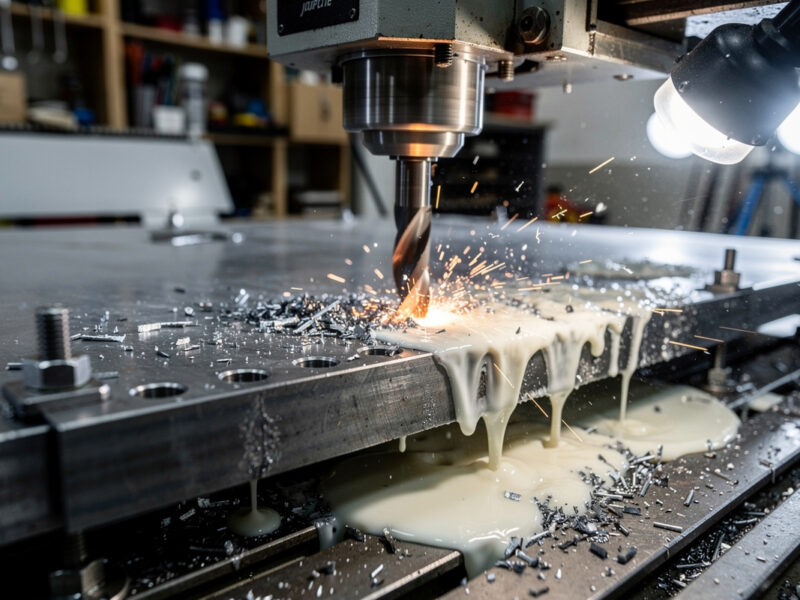
Safety first. The following information is for educational purposes. CNC machining involves high-speed rotating cutters. Always wear eye and ear protection, never leave a running machine unattended, and verify all feeds and speeds for your specific setup.
3D CNC machining splits into two stages: roughing (removing bulk material quickly) and finishing (achieving the final surface). In ~40 words: roughing uses adaptive clearing or pocket strategies to remove most material in deep aggressive passes; finishing uses parallel, scallop, or contour passes with shallow step-overs to achieve the final surface finish. Skipping either stage produces poor results.
This guide covers the toolpath strategies that matter for desktop CNC 3D work — relief carvings, sculpted decorative pieces, and 3D-curved engineering parts. The same principles apply in Fusion 360, VCarve Pro, and most other CAM applications. Understanding the rough/finish split is the difference between professional-looking 3D work and amateurish results.
A quick note: a couple of links below are affiliate links — buy through one and I may earn a small commission at no extra cost to you. I only point to bits I would actually run on my own machine. Details on my disclaimer page.
Why Roughing and Finishing Are Separate
Bulk material removal (roughing) and surface quality (finishing) need different toolpath strategies. Roughing prioritizes speed and chip evacuation; finishing prioritizes surface finish and dimensional accuracy. Trying to do both in one pass produces a slow rough cut with mediocre surface finish.
The standard 3D workflow: roughing removes 90-95% of material with aggressive depth-of-cut and step-over; finishing removes the remaining 5-10% with shallow shallow passes that produce the final surface. Together they’re 30-50% faster than attempting fine cuts in single passes.
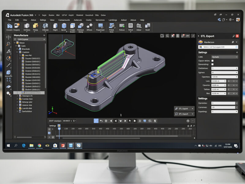
For background on the broader CAM workflow, see our CAM software comparison — Fusion 360 has the strongest 3D toolpaths, VCarve Pro handles wood reliefs, and free CAM applications cover basic 3D adequately.
Adaptive Clearing (Roughing Strategy)
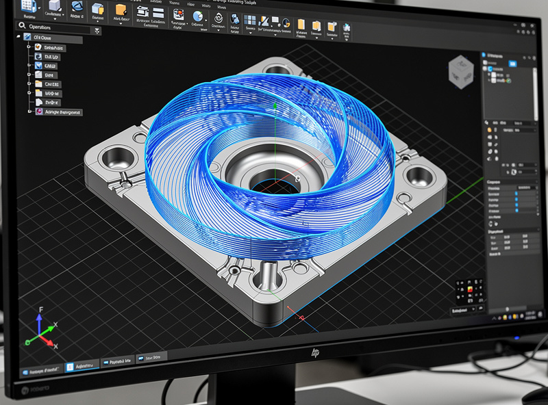
Adaptive clearing is the modern roughing strategy of choice. The algorithm maintains constant chip load by varying step-over dynamically — engaging less of the bit at sharp corners and more in open spaces. The result is consistent cutting forces throughout the cut.
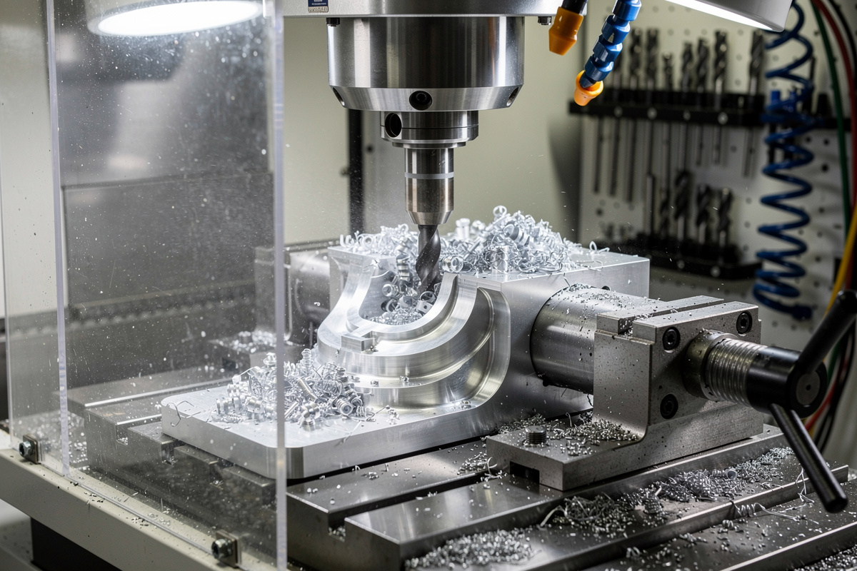
For aluminum specifically, adaptive clearing is the standard. A 1/4″ end mill in 6061 aluminum on a Shapeoko 5 Pro can run 30,000 RPM, 1500mm/min feed, 5mm depth of cut with adaptive clearing — settings that would break the bit with traditional pocket strategies.
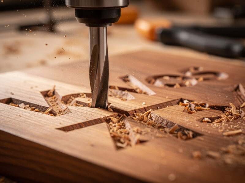
For wood, adaptive clearing also wins. Constant chip load reduces tear-out at corners, produces a more uniform roughed surface, and lets the finishing pass do less work. Setup in Fusion 360: Manufacture → 3D → Adaptive Clearing.
The trade-off: adaptive clearing requires more sophisticated CAM software. Carbide Create’s Pro version added it in version 7.x but the implementation is basic compared to Fusion 360. For users with Fusion 360 access, adaptive clearing should be the default for any 3D roughing operation. It is my default too — once I moved my roughing over to adaptive clearing in Fusion 360, the broken-bit-at-a-corner problem basically disappeared, because the toolpath stops slamming full width into every inside corner.
Traditional Pocket Roughing
Traditional pocket roughing uses fixed step-over and step-down values throughout the cut. Older CAM applications and free options use this approach. It works but produces variable chip load — light cuts in open spaces, heavy cuts at corners.
For wood roughing, traditional pocket strategies are acceptable. The forgiving material handles variable chip load without breaking bits. Setup: 1/4″ end mill, 50% step-over, 6mm step-down, 1500mm/min feed in soft wood.
For aluminum roughing, traditional pocket strategies are dangerous. The variable chip load causes tool breakage at corners. Use adaptive clearing on aluminum even if learning takes longer; the alternative is broken bits at $20-40 each.
Parallel Finishing Strategy
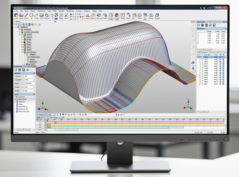
Parallel finishing runs the bit in parallel back-and-forth lines across the surface. Step-over (the gap between adjacent parallel lines) controls the surface finish: 0.1mm step-over produces near-mirror finish in wood; 0.3mm step-over produces visible grooves but cuts faster.
For typical wood relief carvings, 0.2-0.3mm step-over with a 1/8″ ball-nose bit produces good surface finish in reasonable time. Reducing step-over below 0.15mm doubles the cut time without proportional finish improvement.
For aluminum 3D parts, 0.1-0.15mm step-over with a 1/4″ ball-nose bit is standard. Below 0.05mm step-over you’re wasting time; the bit’s tip diameter limits the achievable finish more than the step-over.
Parallel finishing’s limitation: poor performance on vertical or near-vertical walls. For those areas, switch to scallop or contour finishing toolpaths that follow the surface contour rather than running parallel.
Scallop / Constant Step-Over Finishing
Scallop finishing maintains constant step-over distance along the surface contour rather than across the part. The toolpath wraps around curves, producing more uniform surface finish on complex 3D geometry than parallel finishing.
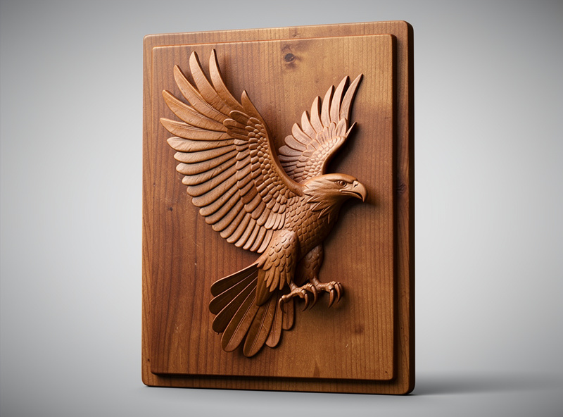
For sculpted relief work (figures, animals, organic shapes), scallop finishing produces visibly cleaner results than parallel. The trade-off is longer cut time — scallop’s path is more complex than parallel’s.
Use scallop on: organic 3D shapes, sculpted reliefs, anywhere parallel produces visible direction artifacts. Use parallel on: flatter surfaces, geometric shapes, anywhere scallop’s longer cut time isn’t justified.
Combined Roughing + Finishing Workflow
The standard 3D CNC workflow: roughing pass with larger end mill, finishing pass with ball-nose bit. The two operations together produce 3D parts faster than either operation alone.
Step 1 — Roughing pass: a 1/4-inch end mill, adaptive clearing strategy, aggressive depth and step-over. Removes 90-95% of material. Time: typically 30-50% of total cut time.
Step 2 — Finishing pass: a 1/8-inch ball-nose bit, parallel or scallop strategy, fine step-over (0.15-0.3mm depending on material). Removes the remaining 5-10% of material and produces final surface finish. Time: typically 50-70% of total cut time.
The bit change between roughing and finishing is the production-time bottleneck. Manual bit changes take 2-5 minutes; automatic tool changers (rare on hobby CNCs) eliminate this. For production work, design parts that batch well — multiple parts using the same toolpath sequence reduces bit changes per finished piece.
For finishing strategy details that depend on material, see our CNC tooling fundamentals guide — different materials respond to different finishing approaches.
Material Considerations for 3D CNC
3D CNC works best on materials that hold detail well and don’t tear out under fine ball-nose bit passes.
Best: Hard maple, walnut, cherry, basswood (soft enough to cut quickly, dense enough to hold detail). Premium options for production decorative reliefs.
Acceptable: Plywood (good face only), MDF (with proper sealing), poplar, soft pine. Budget options that work but produce less crisp detail than premium hardwoods.
Difficult: Open-grained woods (oak, ash) where the grain pattern competes with carved detail. Soft woods (cedar, balsa) that compress under ball-nose pressure rather than cutting cleanly.
Aluminum: Excellent for engineering 3D parts where precision matters more than aesthetic. The challenge is heat management — long finishing passes generate heat that warps thin walls.