Safety first. The following information is for educational purposes. CNC machining involves high-speed rotating cutters. Always wear eye and ear protection, never leave a running machine unattended, and verify all feeds and speeds for your specific setup.
The Complete CNC Pipeline: From Digital Design to Physical Part
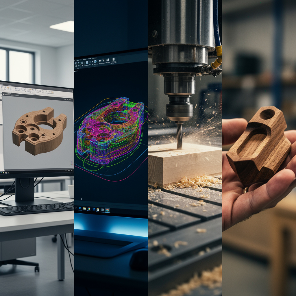
CNC machining involves a multi-stage workflow transforming digital designs into physical parts. Unlike 3D printing where a single slicer program handles everything, CNC requires coordinated CAD design, CAM toolpath generation, machine setup, job execution, and part verification. Understanding each stage enables troubleshooting failures and optimizing results. This comprehensive guide walks through the complete workflow, providing actionable techniques that separate amateur results from professional outcomes.
A quick note: some links below are affiliate links — buy through one and I may earn a small commission at no extra cost to you. I only point to measuring and setup gear I actually keep on my own bench. Details on my disclaimer page.
Stage 1: CAD – Creating the Digital Model
Computer-Aided Design software creates the digital geometry defining your part. The CAD model serves as the foundation for everything that follows—errors here propagate through the entire workflow.
CAD Software Options
Fusion 360 (Autodesk): The hobby and small-business standard. Parametric modeling, integrated CAM, free for personal use. Steep learning curve but professional capabilities. Cloud-based requiring internet connection. Best for mechanical parts, enclosures, and functional components.
FreeCAD: Open-source parametric CAD with Path workbench for CAM. Completely free, offline operation. Less refined than Fusion 360 but capable of excellent work. Suitable for users wanting to avoid Autodesk subscriptions or requiring offline operation.
Blender: Primarily a 3D art package but capable of precision modeling for organic shapes, sculptures, and artistic work. Free and open-source. Different workflow than parametric CAD but powerful for specific applications.
Tinkercad: Browser-based, extremely beginner-friendly. Primitive shapes and boolean operations. Good for learning 3D concepts and simple parts. Limited for complex mechanical work.
Design for CNC Manufacturing
Effective CAD for CNC requires manufacturing awareness. Internal corners will have radii equal to your tool radius—design with this constraint in mind. Sharp internal corners are impossible with round tools; specify relief cuts or accept radiused corners. Avoid undercuts in 3-axis machines unless you plan multiple setups. Design for accessible machining—ensure all features can be reached with standard tool approaches.
Wall thicknesses must accommodate tool diameter. A 6mm end mill cannot cut a 4mm wall. Minimum wall thickness = tool diameter + margin for deflection. For thin walls, use smaller tools or adjust design. Consider tool length—deep pockets require long tools that deflect more. Keep features as shallow as possible for rigidity.
Exporting for CAM
Most CAM software accepts STEP files for 3D models or DXF/SVG for 2D profiles. STEP preserves geometry precisely without tessellation errors. STL files work but introduce faceting that may affect surface quality. For 2D parts, DXF is universal. Ensure proper scale—export in millimeters matching your CAM setup. Verify imported geometry in CAM matches design intent before generating toolpaths.
Stage 2: CAM – Generating Toolpaths
Computer-Aided Manufacturing transforms your CAD model into G-code instructions the machine executes. CAM defines how the tool moves, what speeds to use, and what cutting strategies to employ.
CAM Setup Process
Work Coordinate System (WCS): Define where the part origin sits relative to your stock material. Common setups include top-center of stock, bottom-left corner, or specific feature locations. Consistent WCS placement simplifies machine setup later.
Stock Definition: Specify your raw material dimensions. CAM uses this to calculate safe approaches and clearances. Define stock slightly larger than finished part to allow machining all surfaces.
Tool Library: Create or import tools you actually own. Specify diameter, flute count, overall length, and cutting length accurately. CAM calculations depend on correct tool geometry.
2D Toolpath Strategies
Contour (Profile): Cut along part edges to separate from stock or create features. Can cut inside (pocket) or outside (profile) the boundary. Specify tool compensation (climb vs conventional milling) and multiple depths for deep features.
Pocket: Clear material from enclosed areas. CAM calculates efficient clearing patterns. Specify stepover (typically 40-60% of tool diameter), cutting depths per pass, and finishing passes for clean walls.
Adaptive Clearing: Modern high-efficiency roughing strategy maintaining constant tool load. Reduces cycle times and extends tool life compared to traditional pocketing. Highly recommended for material removal.
Drilling: Plunge operations for holes. Specify peck depths (drill, retract to clear chips, repeat) for deep holes. Spot drills for accurate hole starting; center drills or specific spot drill tools.
3D Toolpath Strategies
Parallel Finishing: Passes parallel to a direction creating consistent tool marks. Good for flat surfaces and gentle slopes. Specify stepover controlling surface finish quality.
Contour (3D): Follows surface contours at constant Z-levels. Produces excellent surface finish on complex shapes. Specify stepdown (Z-interval between passes) controlling finish quality.
Scallop (Radial): Concentric passes from center outward. Good for rounded features and organic shapes. Produces different surface texture than parallel passes.
Rest Machining: Secondary operations cleaning areas larger tools cannot reach. Uses smaller tools to finish corners and tight features after roughing with larger tools.
Speeds and Feeds in CAM
Apply tooling knowledge from previous articles. Set appropriate spindle speeds based on surface speed calculations. Define feeds based on chip load formulas. Conservative starting points prevent tool breakage; increase aggressiveness as you gain experience with your specific machine and materials. Before pushing feeds, make sure the machine is mechanically tidy — unsecured stepper and spindle cables that snag on gantry movement cause false limit triggers that look like mechanical faults. The CNC drag chain guide covers how to size and route cable carriers on X, Y, and Z axes.
Most CAM software includes calculators—input material, tool diameter, flute count, and desired chip load; software calculates appropriate feeds. Verify calculations match tooling charts and adjust based on results.
G-Code Generation and Verification
Generate G-code specific to your machine controller. Grbl, Mach3, LinuxCNC, and proprietary controllers use slightly different dialects. Select correct post-processor for your machine. Review generated G-code in simulator before running on machine—many CAM packages include simulation; standalone simulators like CAMotics provide verification.
Verify rapid moves (G0) clear clamps and fixtures. Check that plunges occur at appropriate locations—not rapid-plunging into material. Confirm coordinate systems and work offsets are logical.
Stage 3: Machine Setup and Workholding
Proper setup ensures accurate parts and safe operation. Rushing setup causes crashes, scrap parts, and potential injury.
Machine Preparation
Verify machine is clean and lubricated. Check that all axes move smoothly without binding. Confirm spindle runs smoothly and collet tightens properly. Home the machine (G28 or home command) to establish machine coordinate reference.
Workholding Setup
Secure stock material to the bed using appropriate methods: clamps on T-slot table, vise for smaller pieces, adhesive methods (double-sided tape, CA glue) for thin stock, or fixture plates for production. Ensure workholding clears tool paths—simulate mentally or with software to verify no collisions.
Place spoilboard (sacrificial material) under workpiece to prevent cutting into bed. MDF or particle board works well. Replace when damaged.
Setting Work Coordinate System (WCS)
Jog tool to your defined WCS origin (typically front-left-top of stock or center of part). Zero X and Y axes at this location using your controller’s set-zero function. For Z, jog tool to touch off on stock surface—use the paper method (slide paper between tool and stock, jog down until it drags); for X and Y, an edge finder gets you precision. The paper trick is fine for wood signs, but once I started cutting parts that had to fit each other, the edge finder paid for itself the first afternoon. Zero Z at this location.
Verify WCS is set correctly by jogging to known locations and checking positions match expected coordinates. Misaligned WCS causes parts to be machined in wrong locations or crashes into fixtures.
Tool Loading and Measurement
Load required tools into spindle or tool changer. For manual tool changes, load first tool and set Z-zero for that tool. For automatic tool changers or machines with a tool length probe, measure each tool length and set in controller.
Verify collet tightness—loose tools create runout and poor finishes or dangerous release during cutting. Do not overtighten; follow manufacturer torque specifications.
Stage 4: Job Execution and Monitoring
With setup complete, execute the G-code program. Active monitoring prevents disasters.
Pre-Flight Checks
Verify correct G-code file is loaded. Check that work coordinates are active (G54 typically). Confirm spindle speed and feed overrides are set appropriately (often start at 50% to verify operation). Ensure emergency stop is accessible and functional.
Run an air cut first—a dry run with Z raised an inch to watch the toolpaths visually. I do this on every new program without exception; thirty seconds of watching air has saved me more clamps and bits than any other habit in the shop. Check that rapids clear clamps and fixtures. Verify coordinate directions match expectations.
Starting the Job
Start spindle before engaging material. Begin program execution. Watch first few cuts obsessively—verify feeds, speeds, and chip formation look correct. Listen for chatter or unusual sounds indicating problems.
Monitor continuously during initial passes. Once verified, periodic checks suffice for long jobs, but remain within earshot and sightline of machine. Never leave running machines completely unattended.
In-Process Monitoring
Watch for chip formation—chips should flow freely without packing in flutes. Listen for chatter—vibration sounds indicate resonance requiring speed adjustment. Check that workholding remains secure—vibration can loosen clamps. Monitor for unusual heat, smoke, or burning smells indicating problems.
Tool Changes
For multi-tool jobs, machine pauses for tool changes. Move to safe location (retract Z fully). Stop spindle. Change tool following proper procedure. Re-measure Z-zero for new tool length. Resume program.
Stage 5: Part Inspection and Finishing
After machining, remove and inspect the part. Determine if it meets specifications or requires rework.
Part Removal
Stop spindle and ensure it has stopped spinning before approaching. Remove clamps or release workholding carefully—parts may shift when pressure releases. Use appropriate tools for removal, never force parts loose risking damage or injury.
Initial Inspection
Remove chips and debris. Visual inspection for obvious defects: missed features, wrong depths, surface finish problems. Measure critical dimensions with digital calipers or micrometers—verify X, Y, Z dimensions match design. Check hole diameters and positions if applicable.
Post-Processing
Remove tabs if part was tabbed to stock. Deburr sharp edges with a deburring tool, file, or sandpaper. Clean surfaces. For aesthetic parts, sand or finish as desired—wood parts may need sanding and finishing; metal parts may benefit from deburring and passivation.
Quality Assessment
Compare finished part to design intent. Document deviations for future adjustment. Determine if dimensional errors result from CAM (wrong coordinates), setup (wrong WCS), tooling (deflection), or machine calibration. Use lessons learned to improve future workflows.
Workflow Optimization and Troubleshooting
Common Workflow Failures
Wrong WCS: Part machines in wrong location or crashes into fixtures. Solution: Always verify WCS before starting; use air cuts to confirm.
Incorrect Depths: Features too shallow or too deep. Solution: Verify Z-zero is set correctly; check CAM stock top definition matches reality.
Chatter and Poor Finish: Vibration causing wavy surfaces. Solution: Reduce depths of cut, adjust spindle speed away from resonant frequencies, verify tool stickout is minimal.
Broken Tools: Excessive forces, chip packing, or crashes. Solution: Verify feeds and speeds are conservative, check chip evacuation, verify workholding is secure.
Building Reliable Workflows
Document successful parameters for materials and tools. Create template CAM setups for common operations. Maintain tool library with actual measured dimensions. Save proven G-code files for repeat jobs. Build checklists for setup procedures ensuring consistency.
As you gain experience, workflows become faster and more reliable. Initial setups taking hours eventually take minutes. The investment in learning pays dividends in productivity and part quality.
From First Job to Fiftieth
Each completed job teaches lessons. Document what worked and what failed. Over time, you develop intuition for speeds, feeds, and strategies appropriate for your specific machine and materials. The workflow described here provides the framework; your hands-on experience fills in the details specific to your equipment and applications.
With workflow mastery established, the next articles address specific practical knowledge: workholding strategies for various situations, safety and dust management, beginner projects building skills progressively, and troubleshooting when things go wrong. Each builds on this workflow foundation, developing comprehensive CNC competence.
Master the Complete CNC Process
With workflow understanding complete, set up your safe CNC workshop with proper dust collection and safety measures. Or learn workholding strategies for various materials.