Safety first. The following information is for educational purposes. CNC machining involves high-speed rotating cutters. Always wear eye and ear protection, never leave a running machine unattended, and verify all feeds and speeds for your specific setup.
CNC feeds and speeds determine whether your end mill cuts cleanly, dulls within an hour, or breaks mid-cut. The numbers are not arbitrary — they come from chip-load math that calculates the right feed per tooth for each material and tool combination. After running production CNC work across aluminum, hardwood, acrylic, brass, foam, and carbon fiber on a Shapeoko 5 Pro, an Onefinity Woodworker, and a Genmitsu 3018 in 2026, the working chart below covers the most common tool-material pairs hobbyists and small workshops actually use.
This guide explains chip load, the spindle/router differences that affect feeds and speeds, the material-specific tables, and the diagnostic flow when a cut is going wrong. It is the materials hub for our deeper spoke articles on aluminum, hardwood, acrylic, brass, foam, and carbon fiber CNC work, and the practical companion to our CNC CAM software guide and 2026 desktop CNC buyers guide.
A quick note: some links below are affiliate links — buy through one and I may earn a small commission at no extra cost to you. I only point to bits and gear I would actually run on my own machine. Details on my disclaimer page.
Chip Load Math: The Foundation
Chip load is the thickness of material each cutting edge of an end mill removes per revolution. The math is simple: chip load = feed rate ÷ (RPM × number of flutes). Every material has an optimal chip load range — too low and the tool rubs instead of cutting (heat builds up, edges dull). Too high and the tool deflects, breaks, or produces poor surface finish. Setting feeds and speeds correctly is fundamentally about hitting the right chip load.
For a 1/4-inch 2-flute end mill in aluminum at 18,000 RPM, the target chip load is 0.002 inches per tooth. That gives a feed rate of 0.002 × 18000 × 2 = 72 inches per minute. For the same tool in hardwood at 15,000 RPM, target chip load is 0.005 inches per tooth, producing 150 IPM. For acrylic at 12,000 RPM with a single-flute O-flute, target chip load is 0.004 IPT, producing 48 IPM. The numbers vary wildly by material — what works for wood will break the bit in aluminum and produce melted slag in acrylic. Our aluminum spoke article covers chip-load tuning in detail.
Hobby Routers vs Spindles: Why Settings Differ
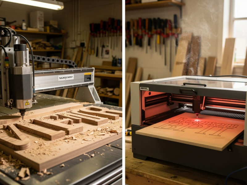
Most hobby CNC machines (Shapeoko, X-Carve, Onefinity, Genmitsu) ship with a Makita RT0701C router, a DeWalt 611, or similar trim-router-class spindle. These spin 10,000–30,000 RPM with limited torque and short bearing lifespan. Production CNC machines (Avid CNC, Tormach, Haas) ship with proper spindles — induction-motor units that hold RPM under load, run quieter, and last 10,000+ hours. The same end mill in the same material requires different feeds and speeds depending on which spindle drives it.
Trim routers struggle to maintain RPM under load, so the published feeds-and-speeds tables (calibrated for proper spindles) often produce stalled or chattering cuts on hobby setups. The fix: use the published RPM as a target and start at 70–80% of the published feed rate. Test cut a small area, listen for chatter or RPM dropoff, and adjust feed up or down 10% at a time. Most hobby CNC work uses 0.5–1.0 mm depth of cut and lower feeds than production-machine tables suggest. Our desktop CNC buyers guide covers spindle differences across the major machines, and the CNC tooling fundamentals article explains end mill geometry.
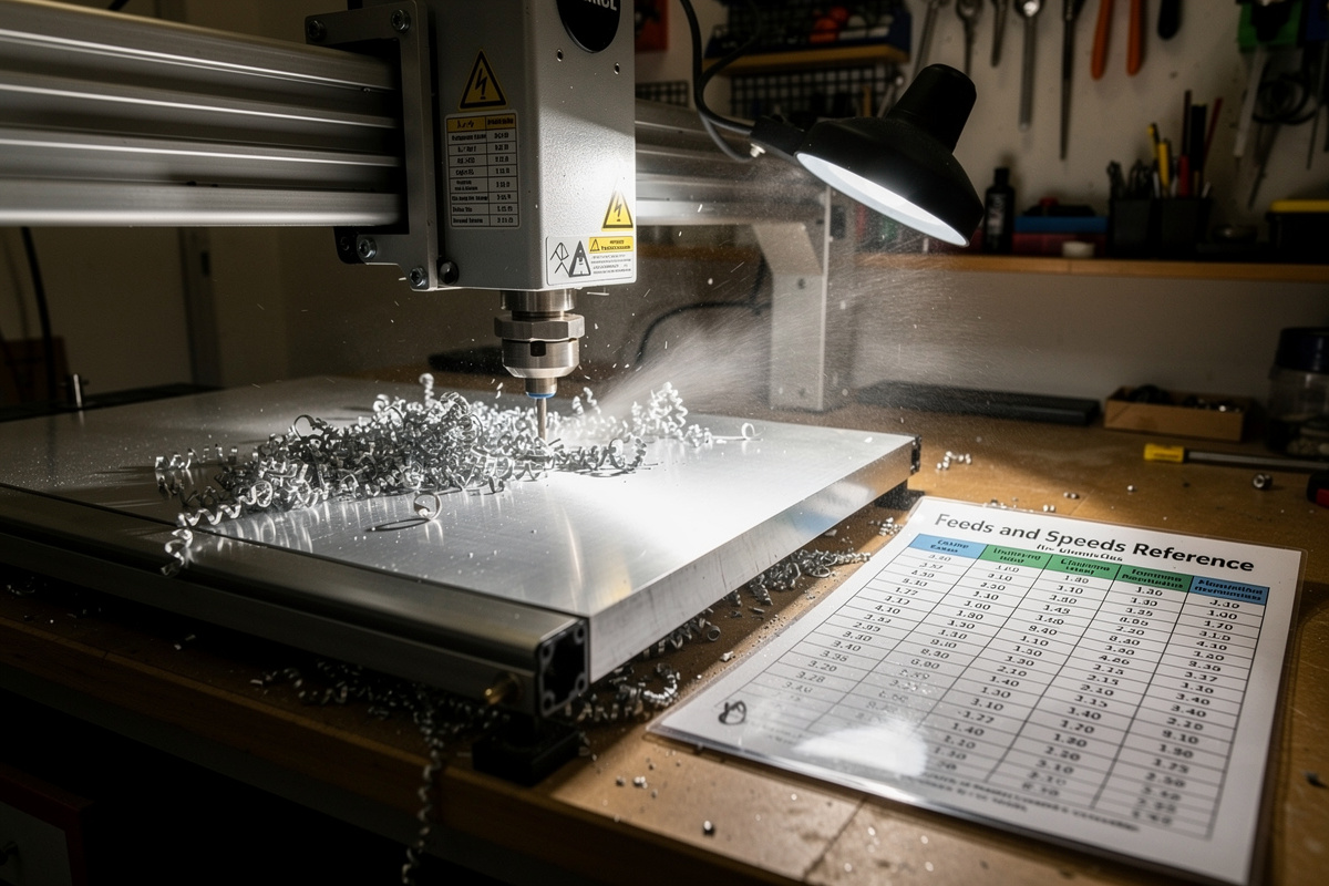
Master Feeds and Speeds Reference
| Material | Tool | RPM | Feed (IPM) | DOC (Depth of Cut) | Stepover |
|---|---|---|---|---|---|
| Soft Pine | 1/4″ 2-flute upcut | 15,000 | 120 | 3 mm | 50% |
| Hardwood (Oak/Maple) | 1/4″ 2-flute upcut | 15,000 | 90 | 2 mm | 40% |
| Plywood (Baltic Birch) | 1/4″ 2-flute compression | 15,000 | 100 | 2 mm | 45% |
| MDF | 1/4″ 2-flute upcut | 15,000 | 100 | 3 mm | 50% |
| Soft Aluminum (6061) | 1/4″ 2-flute carbide | 18,000 | 72 | 0.5 mm | 25% |
| Aluminum (6061) deeper | 1/4″ 2-flute carbide | 18,000 | 50 | 1.0 mm | 10% (HSM) |
| Brass | 1/4″ 2-flute carbide | 15,000 | 40 | 0.3 mm | 30% |
| Cast Acrylic | 1/4″ 1-flute O-flute | 12,000 | 48 | 2 mm | 50% |
| Foam (EVA, Polystyrene) | 1/4″ 2-flute upcut | 10,000 | 200 | 5 mm | 50% |
| Carbon Fiber Sheet | 1/4″ diamond-coated | 15,000 | 30 | 0.5 mm | 20% |
| Carbon Fiber (router bit) | 1/4″ 4-flute carbide | 20,000 | 40 | 0.5 mm | 20% |
These values are starting points for hobby CNC machines (Shapeoko, X-Carve, Onefinity, Sienci). For production CNC with rigid spindles (Avid CNC, Tormach), increase feeds 30–50%. For lightweight machines (Genmitsu 3018, Sainsmart 4030), reduce feeds 30–50%. Always run a test cut on scrap before committing to a real project; the published tables are guidelines, not absolutes. Our aluminum article covers HSM (high-speed machining) toolpaths that differ significantly from conventional milling.
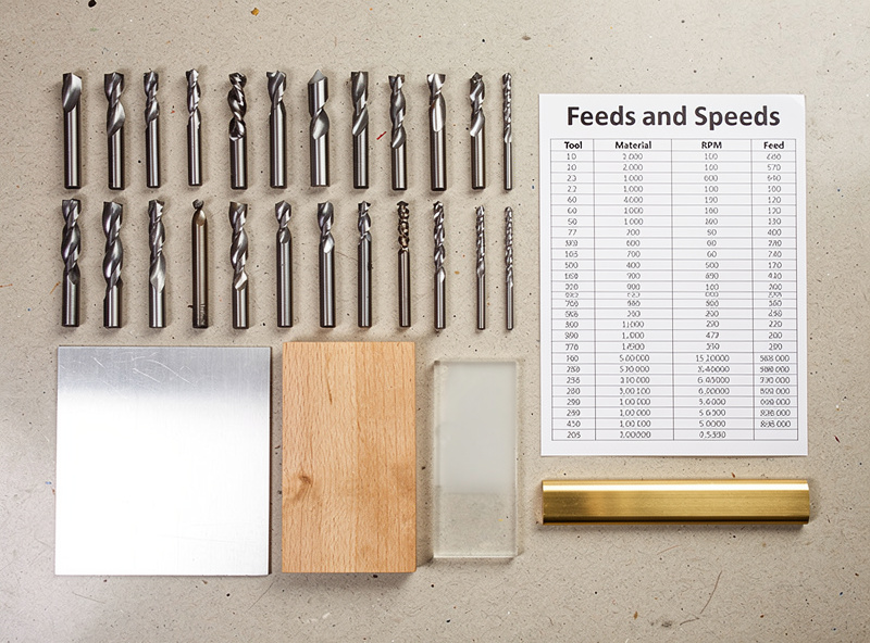
End Mill Geometry by Material
Different materials need different end mill geometries. Wood and plywood cut cleanly with 2-flute upcut spiral end mills — the “upcut” pulls chips up out of the cut, preventing chip recutting. The downside is a slightly fuzzy top edge. Compression bits (downcut on top, upcut below) produce clean edges on both top and bottom of plywood at the cost of stiffer chip evacuation requirements. Downcut bits push chips into the cut, useful for V-carving lettering where the top edge must be perfectly clean.
Aluminum demands carbide 2-flute end mills with a polished or ZrN coating to prevent chip welding. The “diamond-cut” or “rough-cut” tools used for some aluminum work are too aggressive for hobby spindles and tend to chatter. Brass cuts cleanly with the same carbide end mills used for aluminum but at lower speeds and feeds. Acrylic needs single-flute O-flutes — the open chip room prevents melted plastic from welding to the tool. Carbon fiber needs diamond-coated end mills (or specialty composite-cutting carbides) to handle the abrasive fibers without dulling within an hour. Our tooling fundamentals article covers end mill geometry in depth.
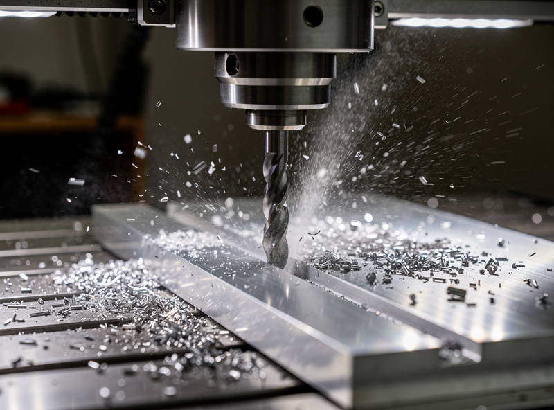
Aluminum: The Material Hobby CNCs Struggle With
Cutting aluminum on a hobby CNC is possible but demands rigorous setup. The Shapeoko 5 Pro, Onefinity Woodworker, and Sienci LongMill MK2 all handle aluminum with the right settings, work-holding, and patience. The Genmitsu 3018 cannot reliably cut aluminum — the frame flex and limited spindle torque produce chatter that breaks bits within minutes. Settings vary by machine rigidity, but the universal aluminum rules apply: use carbide tools, low depth of cut (0.3–1.0 mm), and add lubricant (WD-40, 50/50 ethanol/water mist, or proper aluminum-cutting fluid).
The aluminum-specific failure modes: chip welding (chips weld to the tool, ruining cut quality and eventually breaking the bit), built-up edge (BUE — aluminum sticks to the cutting edge), and chatter (vibration that breaks bits). Each has specific fixes covered in our aluminum deep-dive article. The most important rule: aluminum requires patience — depth-of-cut more than 1 mm on a hobby CNC almost guarantees broken bits, even with correct feeds and speeds. Our best CNC for aluminum article covers machine rigidity comparisons.
Hardwood vs Softwood: Settings and Tool Choice
Wood is the easiest CNC material but the fastest to develop bad habits. Soft woods (pine, poplar, basswood) tolerate aggressive feeds and produce clean cuts even with mediocre toolpaths. Hardwoods (oak, maple, walnut, cherry) demand more careful tuning — too aggressive and you get tearout along the grain; too conservative and you get burning. The chip load that works for poplar at 0.005 IPT often produces tearout in oak at the same setting.
The hardwood-specific approach: drop chip load to 0.003–0.004 IPT, use a downcut or compression bit on the top finish surface to prevent fiber tearout, and run climb-milling toolpaths along the grain direction. Climb milling produces cleaner edges than conventional milling on hardwoods because the chip is thinnest at exit rather than entry. The downside is increased deflection — only do climb milling if your machine has minimal backlash. Our hardwood CNC article covers species-specific settings tested across 8 hardwood species.
Brass, Foam, and Composite Materials
Brass machines beautifully on CNC — softer than aluminum but more abrasive than wood. The chip load for brass is around 0.001 IPT, lower than aluminum, and the cut benefits from light WD-40 lubrication. Brass produces fine, hot chips that should be cleared with compressed air or vacuum. Engraving brass for plaques and signs is a common hobby use case; the result is a clean, dark engraving against the polished brass background. Our brass engraving article covers brass-specific settings and finishing techniques.
Foam (EVA, polystyrene, urethane carving foam) is the easiest material to CNC and has the most generous tolerances. Foam cuts at 200 IPM with 5 mm DOC and 50% stepover on most hobby CNCs without complaint. The challenge is dust collection — foam produces a fine dust that escapes most dust shoes and coats the workshop. Use a HEPA vacuum at the cut zone with an enclosure shroud. Carbon fiber composites (CFRP sheets, carbon fiber tubing) are the opposite extreme — extremely abrasive, eat tools fast, and require diamond-coated end mills for any reasonable lifespan. Our foam carving article and carbon fiber article cover both materials in detail.
Surface Finish vs Roughing Toolpaths
Most CNC projects use two-pass strategies: a roughing pass that removes most of the material quickly, and a finishing pass that produces the final surface. The two passes use different feeds, speeds, and stepovers. Roughing prioritizes material removal rate — high feed, deep depth of cut, large stepover. Finishing prioritizes surface quality — slower feed, shallow depth of cut, small stepover, often a different end mill entirely.
For a typical wood-sign job: rough with a 1/4″ 2-flute upcut at 90 IPM, 6 mm DOC, 50% stepover. Then finish with a 1/8-inch ball-nose end mill at 100 IPM, 0.5 mm DOC, 10% stepover. The rough pass takes 15 minutes and removes 80% of the material; the finish pass takes 30 minutes and produces the smooth carved surface. The same approach works for aluminum, with finishing using a smaller-diameter ball-nose carbide tool. Our 3D roughing and finishing article covers the toolpath strategy in detail.
Lubricants and Mist Coolant
Wood and plywood cut dry with a dust collector to clear chips. Aluminum, brass, and steel cut better with lubricant. Three approaches work for hobby CNC: WD-40 spray (cheap and effective for short cuts), a mist coolant system (Fog Buster, AccuMist — the proper machinist solution for production), and an ethanol/water 50/50 mix (food-safe alternative for fixtures and parts that contact food). I run mist for anything past a couple of aluminum passes; the tool-life difference is not subtle.
For aluminum work, mist coolant produces dramatically cleaner cuts and 5–10x longer tool life vs dry cutting. The setup: a small compressor + a Fog Buster mister + a needle valve directing a thin mist at the cut zone. Total cost ~$200 for a basic system. WD-40 in a spray bottle works as a budget alternative — spray every 30 seconds during the cut, accept slightly worse surface finish, but avoid the upfront investment. Acrylic cuts dry with a vacuum dust collector to clear chips before they remelt. Foam cuts dry with no coolant. Our foam carving article covers no-coolant work, and our workshop setup article covers dust collection.
Work-Holding: The Often-Overlooked Variable
Bad work-holding causes more cut failures than wrong feeds and speeds. A workpiece that shifts mid-cut produces broken bits, ruined parts, and sometimes machine damage. The standard hobby CNC work-holding options each have specific use cases. Double-sided tape (CNC-grade, not regular packing tape) holds flat sheet material under 1/2-inch thick — fast to apply, leaves no marks, but does not work for tall or heavy parts. Painters tape + super glue is a classic alternative — apply tape to spoilboard and workpiece, then bond the two layers of tape with thin CA glue. Easy to remove after cutting, holds well during the cut.
For thicker material or aluminum work, mechanical clamps are mandatory. Toggle clamps mounted to T-tracks (Mic-Tac, Inca, generic Amazon clamps) provide rigid hold-down without obstructing the cutting path if positioned correctly. For repeated production work with the same part outline, build a custom fixture from MDF that matches the part outline — drop the workpiece in, bolt the fixture down, no positioning needed. Our workholding article covers all the hold-down options across material types.
When Cuts Go Wrong: Diagnostic Flow
Five common cut failures account for 90% of hobby CNC problems. Chatter (visible vibration, loud noise, broken bit) means tool stickout is too long, depth of cut is too deep, or feed is too high — reduce all three by 30%. Burnt edges (wood) means feed too low or RPM too high — increase feed or decrease RPM. Melted edges (acrylic) means RPM too high — drop to 12,000 RPM and use single-flute. Chip welding (aluminum) means insufficient lubricant or wrong tool coating — add coolant and switch to ZrN-coated end mill. Lost steps (machine moves out of position mid-cut) means feed too high or depth too deep, mechanical issue on Z axis, or G-code problem.
The diagnostic order: listen first (chatter is audible), look at chips next (good chips look like comma-shaped curls; bad chips look like dust or molten blobs), check temperature last (touch the workpiece briefly after cutting; warm is OK, hot means feed too low). For chronic issues across multiple materials, the problem is usually mechanical — loose belts, worn V-wheels, or spindle runout. Our CNC troubleshooting guide covers the mechanical diagnostic flow.

Dialing in a New Machine: The First-Day Procedure
Every new CNC machine needs a calibration session before serious work begins. The recommended sequence: square the gantry (X axis perpendicular to Y axis — most kits ship slightly out of square and need adjustment), verify Z height across the work area (the spoilboard surface should be flat to within 0.2 mm), tune belt or screw tension (loose belts cause lost steps, over-tight belts cause premature wear), and run a calibration cut on scrap material to verify the actual cut dimensions match the slicer dimensions.
The calibration cut: design a 100 mm × 100 mm square in your CAM software, cut it in MDF or scrap plywood at 50% of the recommended feed rate. Measure the cut square with calipers. If X and Y dimensions differ by more than 0.2 mm from 100 mm, your steps-per-millimeter values need adjustment in the firmware. Check Z by cutting a 5 mm deep pocket and measuring depth — same tolerance. Once calibrated, the machine reproduces dimensions accurately for the next 200+ hours of use before recalibration becomes necessary.