Safety first. The following information is for educational purposes. CNC machining involves high-speed rotating cutters. Always wear eye and ear protection, never leave a running machine unattended, and verify all feeds and speeds for your specific setup.
A VFD turns your single-phase wall power into the three-phase output a CNC spindle needs, and sets the RPM by changing frequency. Get the parameters wrong and you either never reach rated speed, cook the motor at low RPM, or trip on acceleration. The settings that actually matter are the nameplate ones: motor poles, rated voltage and current, maximum frequency, and acceleration time. Set those from the spindle label, not from a forum copy-paste.
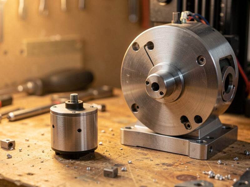
I wired the VFD on my 65mm 1.5kW spindle myself, and the parameters below are the same ones I dialed in on the bench. This is the practical setup walkthrough — what each wire does, which parameters to set and why, how to wire the 0–10V control that lets your G-code set speed, and the sanity checks before the first spin-up. It sits under the CNC spindle and router guide; if you have not chosen a spindle yet, read the router vs spindle comparison and the water vs air cooling guide first. One caution up front: a VFD holds lethal voltage in its capacitors after power-off, so treat it with the same respect you would any mains wiring and let it discharge before you open it.
What a VFD actually does
A variable frequency drive takes your single-phase mains — 230V here in Sweden — and synthesizes a three-phase waveform whose frequency you control. Because an induction spindle’s speed is tied to that frequency, changing frequency changes RPM: a 2-pole spindle runs 24,000 RPM at 400 Hz, half that at 200 Hz. The VFD also manages how fast it ramps up and down so the spindle does not slam to speed and trip out.
The reason you cannot just plug a spindle into the wall is that it needs three phases and variable frequency, neither of which a hobby outlet provides. The VFD is the translator. Everything in setup is about telling that translator the truth about your specific motor — its voltage, current, and pole count — so it drives the spindle within limits instead of guessing. Lie to it on the nameplate values and it will happily overheat or under-drive the motor.
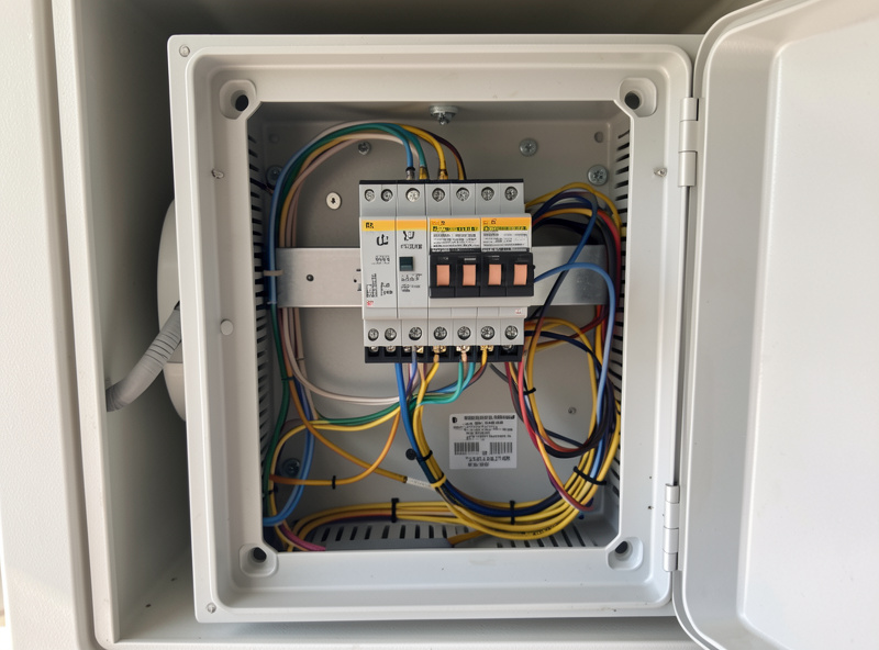
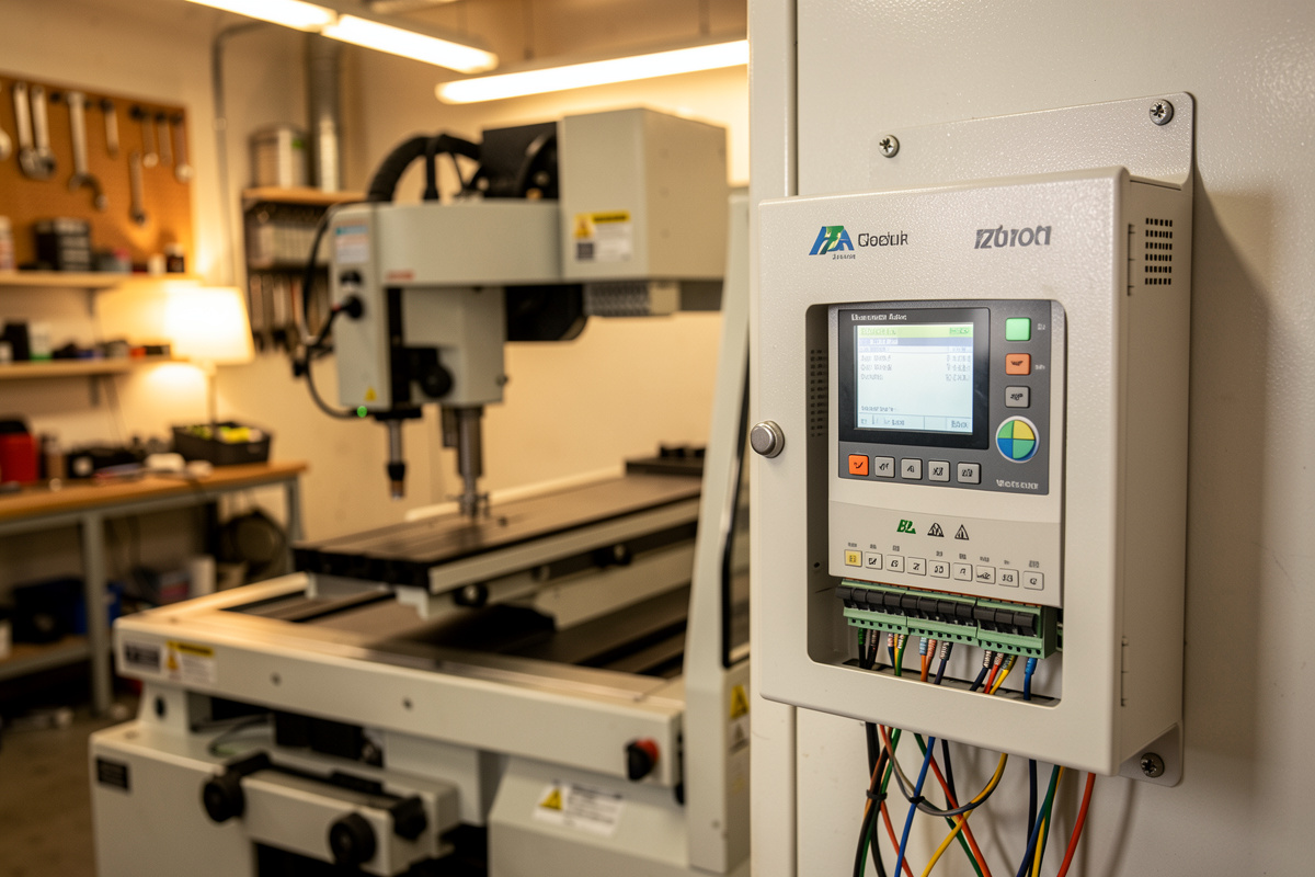
Wiring the VFD: power in, motor out, control
A VFD has three groups of terminals. Power input takes your mains into the terminals usually marked R/S/T or L/N (single-phase units use two of them). Motor output, marked U/V/W, runs to the spindle’s three motor wires — use shielded cable and ground the shield at the VFD end to keep electrical noise out of your controller. The control terminals handle start/stop and speed.
Ground everything: the VFD chassis, the spindle body, and the cable shield — the bonding practice NFPA 79 (the Electrical Standard for Industrial Machinery) lays out for machine tools is built around exactly this kind of drive. A floating spindle is both a shock risk and a noise source that makes your CNC controller see phantom signals. Run the motor cable separately from your signal wiring, not bundled together in the same drag chain lane, because the U/V/W lines are electrically noisy. This separation is the single most common fix for a machine that loses steps only when the spindle runs. Once the power and motor wires are landed and grounded, the rest is parameters and the control wiring.
The parameters that matter
Most hobby VFDs use the familiar PD-code parameter scheme, and you only need a handful set correctly. The critical ones come straight off the spindle nameplate: rated voltage, rated current, pole count, and rated RPM. The rest define the source of the run and speed commands and the acceleration ramp. Set these and ignore the dozens of parameters you will never touch.
Below are the parameters I set, with typical values for a 2-pole 220V spindle. Your rated current comes from your label — do not copy mine; a 1.5kW spindle pulls less than a 2.2kW one. The pole count is almost always 2 on these high-speed spindles, which is what gives 24,000 RPM at 400 Hz. Match rated current accurately, because that is the value protecting the motor from overload.
| Parameter | Sets | Typical value |
|---|---|---|
| PD001 | Run command source | 1 = external terminal |
| PD002 | Frequency source | 1 = external analog (0–10V) |
| PD004 | Base frequency | 400 Hz |
| PD005 | Max operating frequency | 400 Hz |
| PD008 | Max voltage | 220 V |
| PD011 | Min frequency | ~100–120 Hz (keeps RPM safe) |
| PD014 | Acceleration time | 8–15 s |
| PD015 | Deceleration time | 8–15 s |
| PD141 | Rated motor voltage | 220 V |
| PD142 | Rated motor current | From nameplate (e.g. 7–10 A) |
| PD143 | Motor poles | 2 |
| PD144 | Rated motor revolution | 3000 (gives correct RPM display) |
Set the maximum frequency and never run too slow
Maximum frequency caps your top RPM. For a 2-pole spindle rated 24,000 RPM, that is 400 Hz, and PD004 and PD005 both want 400. Setting them higher to chase more RPM overspeeds the bearings and is how people destroy a cheap spindle in an afternoon. Leave the ceiling at the rated value.
The floor matters even more, and it is the rule most newcomers break. An induction spindle loses torque and its own cooling effectiveness at low speed, so running it far below its band — that “low and slow” instinct from hand routing — actively damages it and makes a useless, bogging cut. I keep my minimum frequency around 100 to 120 Hz so the spindle cannot dwell below roughly 6,000 to 7,000 RPM, and I never command lower in G-code. If a material needs less than that, you are reaching for a different process, not a slower spindle. Which materials want what RPM is laid out in choosing spindle RPM by material.
The 0–10V link for automatic speed control
The upgrade that turns a spindle from a quieter router into a properly integrated tool is wiring the VFD’s analog input so your controller sets the speed. The VFD has an analog input terminal (often VI or AVI) and a 10V reference and ground; your CNC controller’s PWM or 0–10V spindle output drives that input. With PD002 set to external analog, an S18000 in your G-code now produces 18,000 RPM directly.
That means CAM controls the whole cut. A program that roughs aluminum at 10,000 RPM and finishes at 12,000, or a job that drops speed for a plastic operation, just works — no reaching for a dial mid-program. On a GRBL controller you map the spindle PWM output to the VFD analog input, scale it so full PWM equals 400 Hz, and verify the commanded versus actual RPM at a few speeds. Getting this link right is what makes repeatable speeds and feeds possible, the same numbers I rely on in the feeds and speeds chart.
As an Amazon Associate I earn from qualifying purchases. If you are buying the whole package at once, a matched spindle and VFD kit spares you the headache of mismatched current ratings and connectors.
First spin-up and sanity checks
Before the first start, double-check the grounds, confirm rated current matches the nameplate, and make sure nothing is in the collet. Power up, command a low speed first, and watch and listen: the spindle should ramp smoothly, run true, and not trip. Let it idle up through its range in steps, checking that the displayed RPM matches what you commanded once the 0–10V link is in.
If it trips on acceleration, lengthen the ramp time; if it never reaches top speed, recheck the max frequency; if the displayed RPM is wrong, fix PD144. A spindle that vibrates or runs hot at idle has a mounting, balance, or bearing problem, not a parameter one — check runout before you cut, using the method in spindle runout and bearing maintenance. Once it spins up clean, ramps without tripping, and tracks commanded RPM, you are ready to cut. For where the spindle fits among the upgrades worth doing, see CNC router upgrades that actually pay off.
Frequently Asked Questions
What VFD parameters are most important to set?
The nameplate values: rated motor voltage, rated current, pole count, and rated RPM, plus maximum frequency and acceleration time. On PD-code drives that is PD141, PD142, PD143, PD144, PD005, and PD014. Set rated current accurately because it protects the motor from overload.
What maximum frequency should I set for a CNC spindle?
Match it to the spindle’s rated RPM. A 2-pole spindle rated 24,000 RPM runs at 400 Hz, so PD004 and PD005 should both be 400. Setting it higher to chase more RPM overspeeds the bearings and can destroy a cheap spindle quickly.
Why should I not run a VFD spindle at very low RPM?
Induction spindles lose torque and their own cooling effectiveness at low speed, so running far below the rated band bogs the cut and overheats the motor. Set a minimum frequency around 100 to 120 Hz and never command below roughly 6,000 to 7,000 RPM.
How do I make my CNC control the spindle speed automatically?
Wire the controller’s 0 to 10V or PWM spindle output to the VFD analog input, and set the frequency source parameter to external analog. Then an S-word in your G-code sets the actual RPM, so CAM controls speed and tool changes can adjust it automatically.
Do I need shielded cable for the spindle motor wires?
Yes. The VFD output is electrically noisy, so use shielded cable for the U/V/W motor wires, ground the shield at the VFD end, and route it away from signal wiring. This is the most common fix for a machine that loses steps only when the spindle runs.
Is a VFD dangerous to wire?
It carries mains voltage and holds lethal charge in its capacitors after power-off, so treat it like any mains wiring: power down, let it discharge before opening, ground the chassis and spindle, and double-check connections before the first spin-up. If unsure, have an electrician verify it.