Safety first. The following information is for educational purposes. CNC machining involves high-speed rotating cutters. Always wear eye and ear protection, never leave a running machine unattended, and verify all feeds and speeds for your specific setup.
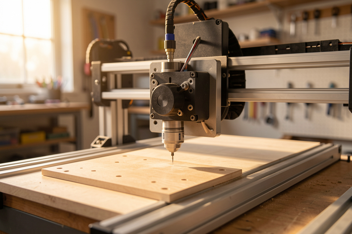
The Z-axis is where most hobby CNC machines quietly lose the rigidity fight. The gantry gets all the attention because you can watch it flex, but the Z is the cantilevered arm hanging off the front of it — a short throw, often a single skinny rail, a thin spindle plate, and a lead screw doing double duty as a structural member. Everything the cutter does in X and Y eventually feeds back through that stack, and when the stack is the weakest link, you see it as chatter, stepped walls, and a taper you can’t tram out no matter how square the machine looks at rest.
I think about every upgrade through a single lens: total cost of rigidity. Stiffness on a hobby machine is a budget you spend where it buys the most cut quality per dollar, and the Z-axis is frequently the highest-return line on that budget — but only if it’s actually your bottleneck. Before you order a thicker plate or a ball screw, you have to prove the Z is the part that’s moving. This is the deep dive on why stock Z assemblies flex, how to diagnose whether yours is the limiting factor, and which upgrades pay off in what order.
A quick note: some links below are affiliate links. Buy through one and I may earn a small commission at no extra cost to you. I only point to parts I’d actually bolt onto a machine on my own bench — details on my disclaimer page.
Why the Stock Z-Axis Is the Weak Link
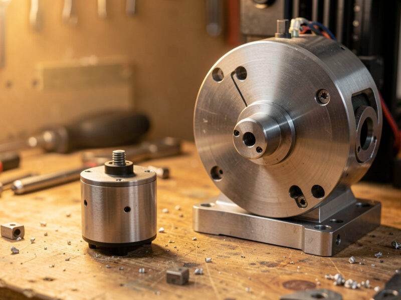
Look at how a Z-axis is built and the problem is structural, not mysterious. The spindle hangs forward of the rails on a plate, and the cutting force at the tip of the bit acts on a lever arm equal to that overhang plus the tool stick-out. A side load at the cutter — exactly what you get in any contour or adaptive pass — becomes a bending moment that the rails, the carriage, and the plate all have to resist. Deflection of a cantilever scales roughly with the cube of its length and inversely with stiffness, so a longer, thinner, less-supported Z gives up rigidity fast.
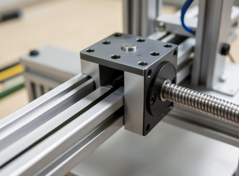
Three things gang up on a stock assembly. First, a single linear rail or a pair of round shafts can’t resist twist well — the carriage can rack slightly under a side load, letting the spindle nose move even when the rail itself barely bends. Two rails set apart resist that racking far better than one rail or two close shafts. Second, the spindle mounting plate is often too thin; an aluminum plate that’s fine in pure compression bows under a bending load, and any flex there shows up magnified at the tool tip. Third, the lead screw is doing structural work it shouldn’t — on many designs the screw and its anti-backlash nut are part of what locates the carriage vertically, and screw whip plus nut play add compliance right where you don’t want it.
The result on the part is specific and recognizable. A flexing Z lets the cutter walk away from the commanded depth under load, then spring back when the load drops — that oscillation is chatter, and it leaves a rippled, washboard finish on a wall. Worse, if the Z deflects consistently in one direction during a profiling pass, you get a tapered wall: the top of the cut, where the Z is more extended, opens up wider than the bottom. People chase that taper with tramming, new bits, and slower feeds for weeks before realizing the axis itself is bending. My troubleshooting guide for desktop CNC walks the broader symptom tree, but stepped or tapered vertical walls point hard at the Z.
Diagnose It Before You Spend a Krona
Rigidity upgrades are only worth it on the axis that’s actually moving, so I diagnose before I buy. The tool is a dial indicator — the same one I use for tramming — and the method is a static push test that isolates deflection by axis. Power the machine so the steppers hold position, but don’t cut. Then push on the cutter itself with measured hand force and read where the movement comes from.
Here’s the checklist I run, and it’s worth doing in this exact order:
- Mount the indicator off-machine, on the bed or a separate stand, with the tip touching the side of the installed bit near the tip. You want to measure the tool’s movement relative to the workpiece, not relative to the gantry.
- Push the bit sideways in X, then in Y, with firm, repeatable hand pressure, and record the indicator swing each way. This captures gantry, rail, and Z deflection combined for each direction.
- Push the bit straight back (toward the column) and pull it forward — this loads the Z cantilever and the spindle plate most directly. A big reading here with a small reading at the gantry base is your smoking gun.
- Move the indicator to the spindle plate, then to the gantry beam, and repeat. By walking the indicator down the structure you find where the deflection appears versus where it doesn’t. If the plate moves a lot relative to the rail carriage, it’s the plate. If the carriage racks relative to the rail, it’s the rail count. If the whole gantry leans, the Z isn’t your problem.
- Compare the numbers, don’t judge absolutes. The axis with the largest deflection under the same push is your bottleneck. Rigidity upgrades anywhere else are wasted money until you fix that one.
This five-minute test has redirected more of my upgrade spending than any spec sheet. More than once I’ve been certain the Z was flexing, run the push test, and found the gantry beam or the V-wheels were the real culprit — at which point a Z ball screw would have been pure waste. The push test is the cheapest tool in the whole total-cost-of-rigidity equation, because it stops you spending on the wrong axis.
The Upgrade Ladder, Cheapest Stiffness First
Once the push test fingers the Z, the options stack from cheapest to most involved, and that’s roughly the order of return on investment too. I work up the ladder rather than jumping to the most expensive fix, because each rung often buys enough rigidity to make the next one unnecessary.
Thicker spindle/gantry plate. If your push test showed the plate bowing relative to the carriage, this is the highest-return fix on the whole machine. A stock plate replaced with a noticeably thicker billet plate stiffens the most-deflecting member for the least money and effort. It’s a bolt-on on most machines, and because plate bending is often the dominant term, it can shrink Z deflection dramatically on its own. This is where I start whenever the indicator says the plate is the mover.
Dual linear rails. If the carriage racks — moves in twist rather than the plate simply bending — going from a single rail or round shafts to two parallel profiled linear rails set as far apart as the design allows is the fix. Two rails resist the twisting moment that a single rail can’t, and profiled rail blocks have far less play than V-wheels or round-shaft bushings. A pair of MGN12 linear rails with carriages is the common hobby-Z size, and the width you can mount them at matters more than the rail size itself — spread them as wide as the plate allows.
Lead screw to ball screw. This is the total-cost-of-rigidity headline. A standard lead screw with an anti-backlash nut has inherent compliance and backlash; a ball screw runs on recirculating bearings with near-zero backlash and far higher axial stiffness. On the Z specifically, where the screw helps hold position against the spindle’s weight and the cutting load, swapping to a ball screw tightens position control and kills a real source of give. A SFU1204 ball screw kit is the typical hobby-Z choice — but it’s also the most involved swap, often needing new bearing blocks and a coupler, so it earns its place only after plate and rails are sorted.
Longer Z travel — with eyes open. Plenty of people want more Z travel for thick stock or a fourth axis, and longer Z assemblies are sold for exactly that. Just understand the tradeoff against the cantilever math above: a longer Z is a longer lever, and unless its rails and plate scale up to match, you’re buying travel and giving back rigidity. If you go long, go stiff at the same time — wider rail spacing, a thicker plate, the works. Don’t add travel to a Z that already failed the push test.
For people who’d rather buy the whole bracket-rail-plate package matched to their machine, a purpose-built CNC Z-axis upgrade kit bundles the stiffer plate and rails for popular hobby machines and skips the parts-sourcing. I still run the push test first to confirm it’s the right spend.
The Spindle-Weight Interaction Nobody Mentions
Here’s the upgrade trap I watch people fall into: they stiffen the gantry, then hang a heavier spindle off the Z and wonder why it got worse. Z rigidity and spindle weight are coupled. A heavier spindle is a bigger static load on the same cantilever, a bigger inertial load when the Z accelerates, and a bigger overturning moment that the rails and plate have to resist at every position. The Onefinity Woodworker I keep as my ball-screw rigidity reference handles a heavier head because the whole Z stack was built for it; bolt that same head onto a flexy stock Z and you’ve just loaded the weak link harder.
So the sequencing matters. If a VFD spindle swap is on your list — and on my own daily-driver Shapeoko Pro the move to a 65mm 1.5kW air-cooled VFD spindle was one of the best upgrades I’ve made — do the Z stiffening first or alongside it, not after you’ve discovered the heavier head made the chatter worse. A spindle upgrade raises both the cutting forces you can apply and the weight the Z must carry, which is double the reason the Z needs to be ready for it. The same logic runs through how I’d choose a machine for cutting aluminum on a desktop CNC, where every gram and every bit of deflection shows up in the finish.
When Not to Bother With the Z
The flip side of total cost of rigidity is knowing when the Z isn’t where your money goes. If the push test shows the Z is already stiff — small deflection at the plate and carriage relative to a big number somewhere else — then a Z upgrade buys you almost nothing, and you’ve found your real bottleneck elsewhere. Spend on that instead.
The two usual better targets are the spindle and the frame. If your gantry beam or its uprights are leaning under load, no Z plate will fix a part that’s moving because the whole arch is flexing — frame stiffening or a more rigid machine is the answer, which is the whole reason I rank machines by gantry rigidity in my best desktop CNC roundup and the Onefinity vs Shapeoko comparison. And if the machine is rigid but the cut quality is poor, the limiter may be the spindle’s runout or power, not deflection at all — a different fix entirely.
There’s also a feeds-and-speeds answer that sidesteps the spend. A genuinely flexy machine you can’t or won’t upgrade yet can still cut clean if you reduce the load: lighter depth of cut, the right chipload, and conventional milling instead of climb on the flexiest setups all reduce the side force the Z has to resist. I lay that reasoning out in the aluminum feeds and speeds guide and the broader feeds and speeds chart — sometimes the cheapest rigidity upgrade is asking less of the axis in the first place. Match the cut to the machine you have, prove the bottleneck before you buy, and spend your rigidity budget where the indicator — not the marketing — tells you to.
Frequently Asked Questions
How do I know if my CNC Z-axis is causing chatter?
Run a dial-indicator push test. Mount the indicator off-machine touching the bit near the tip, then push the cutter back and forth in the Z direction with firm hand pressure and read the deflection. Compare that to pushing in X and Y and against the gantry beam. If the Z and spindle plate move far more than the rest of the structure, the Z is your bottleneck. Tapered or stepped vertical walls point the same way.
What is the cheapest CNC Z-axis upgrade that actually helps?
A thicker spindle mounting plate, when the push test shows the plate bowing relative to the carriage. Plate bending is often the dominant deflection term, so a thicker billet plate stiffens the most-flexing member for the least money and is usually a bolt-on. Start there before spending on rails or a ball screw.
Should I upgrade to a ball screw on the Z-axis?
A ball screw gives near-zero backlash and much higher axial stiffness than a lead screw with an anti-backlash nut, which tightens Z position control under load. It is worth it, but it is the most involved swap, often needing new bearing blocks and a coupler. Do the thicker plate and dual rails first, then add the ball screw if deflection remains.
Does a heavier spindle make Z-axis flex worse?
Yes. A heavier spindle is a larger static load, a larger inertial load when the Z accelerates, and a larger overturning moment on the rails and plate. If you plan a heavier VFD spindle, stiffen the Z first or at the same time, not after, or the heavier head will load the weak link harder and make chatter worse.
When should I not bother upgrading the Z-axis?
When the push test shows the Z is already stiff and the big deflection is somewhere else, such as the gantry beam leaning or the spindle itself. A Z upgrade buys almost nothing then. Spend on frame rigidity or the spindle instead, or simply reduce depth of cut and use conventional milling to ask less of the axis.