Safety first. The following information is for educational purposes. CNC machining involves high-speed rotating cutters. Always wear eye and ear protection, never leave a running machine unattended, and verify all feeds and speeds for your specific setup.
A desktop CNC drills steel bolt holes to ±0.005 inch and a MIG welder closes the assembly in 10 minutes. On a 4-foot steel frame with 16 bolt holes, the CNC-then-weld workflow saves about 45 minutes of layout, punching, and hand drilling.
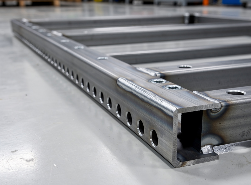
In my workshop the CNC router handles aluminum and wood most days, but the steel projects are where the machine’s real value shows because steel is unforgiving about hole placement — a bolt hole that is off by 1/8 inch means the part does not fit, and the fix is either slotting the hole with a die grinder or re-drilling, both of which ruin the clean fabrication look. The CNC eliminates that class of error entirely. The hybrid workflow — CNC the holes and profiles, then weld the assembly — produces steel structures that fit together without a grinder, because the CNC-drilled holes are in exactly the right place and the parts align on the first dry-fit. This article covers the CNC-side workflow for steel fab: tooling, feeds and speeds, and how to export a DXF from CAD that a welder can actually read. The welding side — MIG settings, joint design, and technique — lives on homewelder.com’s MIG welding guide, where voltage, wire speed, and gas selection are covered in detail.
What a Desktop CNC Can Do to Steel
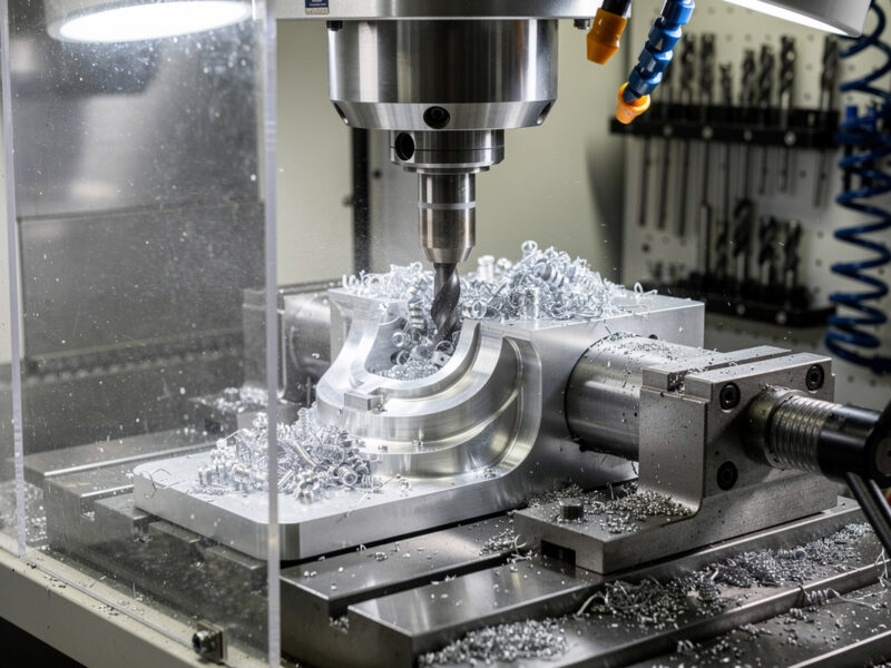
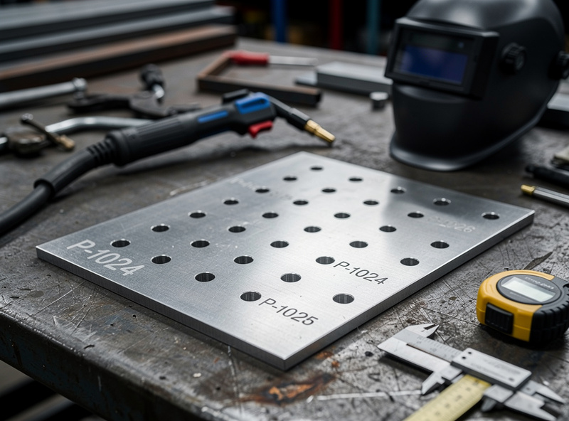
On my machine — a mid-size desktop router in the 3018-to-6040 footprint — I do not try to cut through steel plate. The router can drill holes in steel up to about 1/8 inch (3 mm) thick with a carbide drill bit, and it will engrave layout lines and bend marks on the steel surface cleanly. The frame is not rigid enough for slot milling. For anything thicker than 1/8 inch, I run the CNC as a precision punch — it marks every hole center with a spring-loaded center punch or an engraving bit, and I finish the holes on a drill press. The value is the positional accuracy, not the material removal. On a recent bracket job my CNC placed 16 hole centers within 0.005 inches of each other in 2 minutes. The same layout by hand would have eaten 20 to 30 minutes of scribing and punching, and at least one of those punches would have walked off.
My carbide-only lesson. The first time I tried to drill 16 bolt holes through 1/4 inch steel plate on the CNC I ignored everything I now tell people. I loaded an HSS jobber bit, set 8,000 RPM, no peck, a thin squirt of WD-40 on the first hole, and started the program. The bit smoked by hole 4, the chips welded to the flutes by hole 6, and on hole 8 it snapped clean off in the work. I had to drill it out with a left-hand bit and re-clamp the plate. Lesson burned in: coated carbide only, peck cycle at 0.5 mm, cutting fluid on every hole, and budget about 45 seconds per hole. That is the rule that drives the table below.
The tooling for steel on a desktop CNC is specific and unforgiving:
- Carbide drill bits only. Carbide bits only. HSS dulls in 3 holes. Carbide lasts 50–100 holes with proper cooling at the 8,000–20,000 RPM range a router spindle delivers.
- Cutting fluid is mandatory. A squirt of Tap Magic or WD-40 on each hole before the bit touches down. Dry carbide in steel at 10,000 RPM welds the chip to the cutting edge within seconds.
- Peck drilling cycle. The CNC retracts the bit every 0.5–1.0 mm of depth to clear chips. Without pecking, the flutes pack with steel chips and the bit snaps. A 0.125 inch carbide drill through 0.125 inch steel with a 0.5 mm peck depth takes about 45 seconds per hole, which is slower than a drill press but faster when you account for layout time.
| Steel Thickness | Operation | Bit | RPM | Feed (mm/min) | Peck Depth |
|---|---|---|---|---|---|
| 0.063 in (1.6 mm) | Drill through | 1/8 carbide | 8,000 | 80 | 0.5 mm |
| 0.125 in (3.2 mm) | Drill through | 1/8 carbide | 6,000 | 50 | 0.5 mm |
| 0.125 in+ | Mark centers only | Spring punch | — | — | — |
| Any | Engrave layout | Carbide engraver | 10,000 | 150 | 0.1 mm |
Safety note on the spinning end. A desktop router spindle at 10,000 RPM is still a rotating power tool, and OSHA 29 CFR 1910.212(a)(1) requires one or more methods of machine guarding to protect the operator from the point of operation, in-running nip points, and rotating parts. On my setup that means a polycarbonate enclosure around the gantry, a hard E-stop within arm’s reach, and no loose sleeves anywhere near the spindle when steel chips are flying. ANSI B11.0 covers the broader machinery safety risk-assessment framework and is the reference I work from when I add any new fixturing or guarding to the router.
The CAD-to-Cut-List Workflow
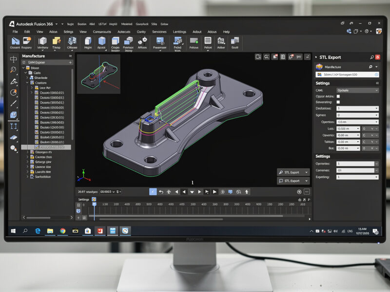
In my setup the hybrid fabrication workflow starts in CAD with a single model that contains both the parts and the assembly. Fusion 360 is the tool I use because it exports both the CAM toolpaths for the CNC and a 2D drawing with dimensions for the welder. One model, two outputs. The workflow is:
- Model the entire assembly in Fusion 360 — every plate, bracket, and tube — with bolt holes modeled as exact-diameter circles.
- Export each steel plate as a separate component and generate a CAM setup for each one. The CAM setup includes the drill operations for every hole and an engrave operation for the part number and bend lines.
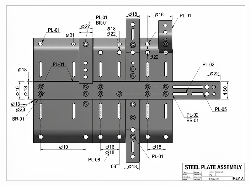
- Export a 2D drawing with overall dimensions, hole callouts, and a cut list. This drawing is what the welder uses to cut the steel stock to rough size before it goes on the CNC.
- The CNC drills the holes and marks the bend lines. The parts come off the CNC, get cut to final size on a chop saw or bandsaw along the marked lines, and go to the welding table.
The part numbering is the small detail that makes this workflow work. Every steel plate on my bench gets an engraved part number (P1, P2, B1, B2, etc.) that matches the cut list. The weld drawing references those part numbers, so the welder picks up P1, sees that it mates to B1 and B2, and the bolt holes align because the CNC placed them from the same CAD model. No part numbers means a puzzle. A puzzle costs 15 minutes per assembly in orientation and rework. I have paid that price exactly once.
Edge prep matters before any weld. One thing the CNC side does not solve is edge cleanliness for the welder. AWS D1.1 Structural Welding Code — Steel calls out in §5.15 that surfaces and edges to be welded must be smooth, uniform, and free of fins, tears, cracks, and other discontinuities that would adversely affect weld quality. In practice that means after the chop saw or bandsaw cuts the CNC-marked lines, I hit every joint edge with a flap disc on the DeWalt grinder before the part hits the welding table, so the root pass has clean parent metal to fuse to. The CNC gets the holes right; the operator still owns the edges.
Frequently Asked Questions
Can a desktop CNC router cut through steel plate?
No. Desktop CNC routers do not have the rigidity or spindle torque to cut through steel. They can drill holes up to about 1/8 inch (3 mm) thick with carbide bits and can engrave layout lines, but actual steel cutting requires a mill, a plasma cutter, or a bandsaw. The CNC value in steel fab is positional accuracy, not material removal.
What is the best CAM software for drilling steel plate on a desktop CNC?
Fusion 360 for integrated CAD-to-CAM workflow. For simpler jobs, Estlcam or Carbide Create handle drill and engrave toolpaths. The critical CAM setting is the peck drilling cycle with chip-breaking retracts every 0.5 mm — this prevents carbide drill bits from snapping in steel.
How do I prevent the steel plate from moving on the CNC bed?
Clamp the steel plate to a spoilboard with at least 4 hold-down clamps — steel has 3× the cutting force of aluminum and will walk across the bed if clamped only at the edges. A thin sheet of rubber shelf liner between the steel and the spoilboard adds friction and damps vibration. For small parts, superglue the steel to a sacrificial MDF board and release with acetone after machining.
Can I use the same end mills for aluminum and steel?
No. Aluminum-specific end mills have sharper cutting edges and polished flutes that work poorly on steel. Steel requires carbide tooling with a coating (TiN or TiAlN) and a less aggressive rake angle. Using an aluminum end mill on steel dulls it in seconds. Drill bits should be carbide for steel, HSS for aluminum only.
What file format does a welder need from the CNC workflow?
A printed 2D drawing with overall dimensions, hole locations, and part numbers. The welder does not need the STL or DXF — they need a clear fabrication drawing that matches the engraved part numbers on each piece. A PDF of the assembly drawing with a cut list table is the minimum deliverable from CNC to welder.
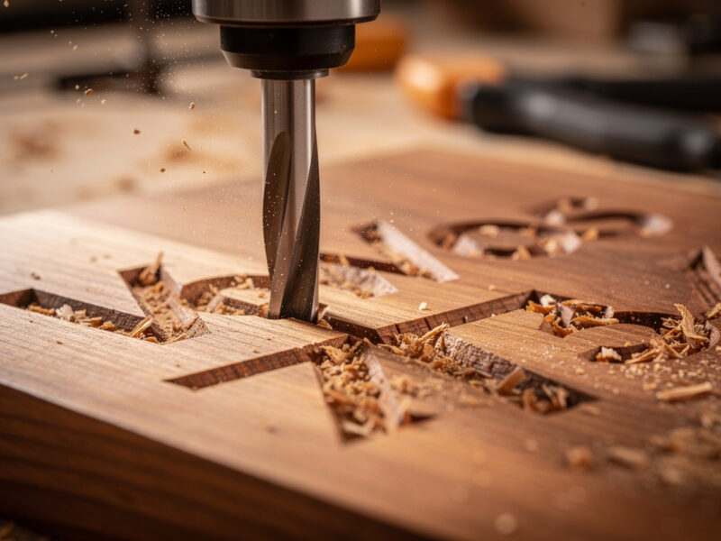
How do I mark bend lines on steel with a CNC router?
Use a 60-degree carbide engraving bit at 0.1 mm depth and 150 mm/min feed rate. The engraved line is about 0.3 mm wide and clearly visible on steel. Spray the steel surface with layout fluid (Dykem blue) before engraving for maximum contrast. The engraving bit skates across the surface without digging in, leaving a bright line on the blue background.