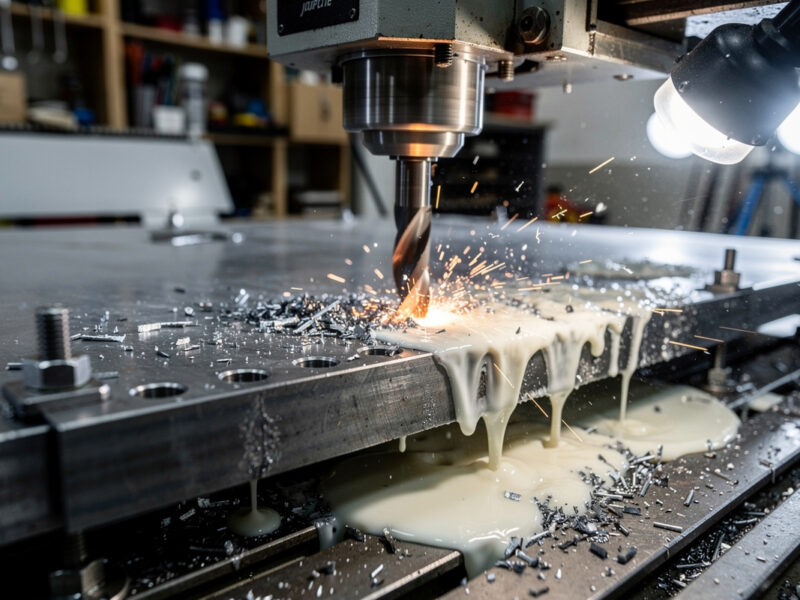
Safety first. The following information is for educational purposes. CNC machining involves high-speed rotating cutters. Always wear eye and ear protection, never leave a running machine unattended, and verify all feeds and speeds for your specific setup.
Fusion 360 is the design tool for both CNC routing and 3D printing — the same model exports to G-code for the CNC and STL for the slicer. That convenience hides a real engineering decision: for any given functional part, which fabrication path produces a better result, faster, at lower cost? After running the same designs through both pipelines for two years, the answer is clearer than online debates suggest. CNC wins on structural strength, surface finish, and material range; 3D printing wins on internal geometry, customization, and short-run economics.
This guide walks the workflow from a single Fusion 360 model through both export paths, compares finished-part properties on real test pieces, and gives a decision framework for choosing the right tool. The downstream slicer software side covers the post-STL workflow in detail; this article focuses on the choice point in Fusion 360.
The Two Workflow Paths from One Model
Fusion 360 supports both pipelines natively, but the export steps are different.
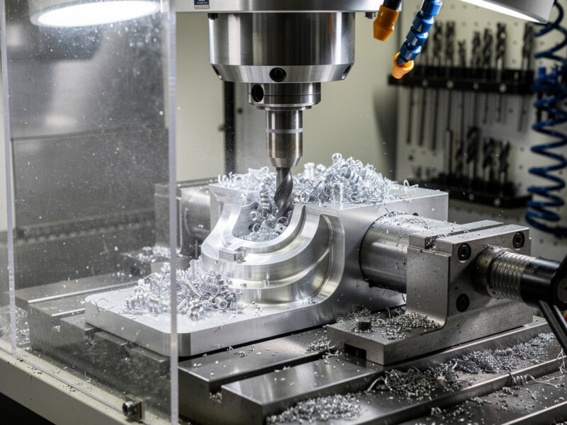
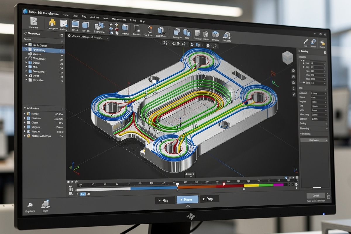
Path A: Fusion 360 → CAM workspace → G-code → CNC. Switch to the Manufacture workspace, set up stock, define toolpaths (2D pocket, contour, 3D adaptive, finish), simulate the cut, post-process to G-code for your specific machine controller (Mach3, GRBL, Buildbotics, etc.). The G-code drives the actual CNC.
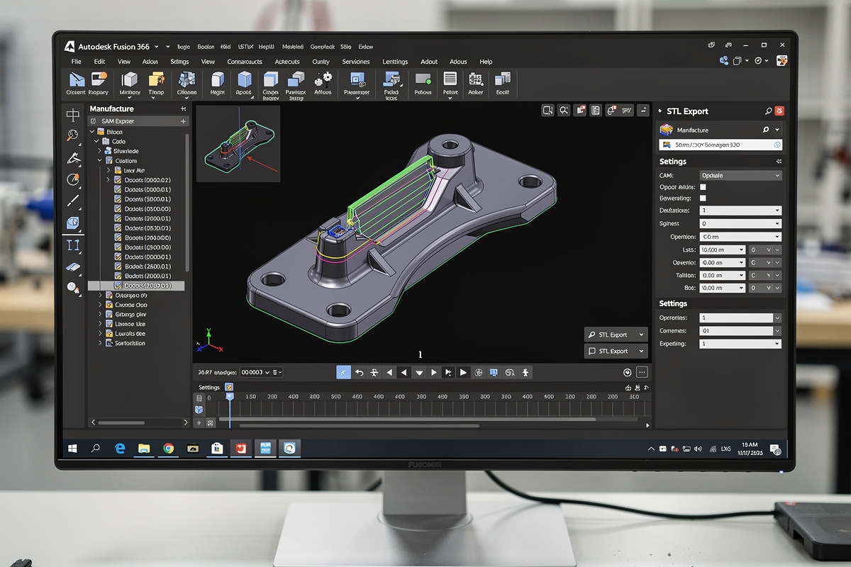
Path B: Fusion 360 → STL export → slicer → 3D printer. File menu → Export → STL. Open the STL in Cura, PrusaSlicer, OrcaSlicer, or Bambu Studio. Configure layer height, infill, supports, and material. Slice to G-code. Send to printer.
The two paths share Fusion 360 design time but diverge completely after export. CAM toolpath setup typically takes 15–30 minutes for a non-trivial part. STL export plus slicing typically takes 5–10 minutes. The downstream time difference is the first cost worth knowing about.
Strength and Material: Where CNC Wins
For load-bearing or structural parts, CNC produces objectively stronger results in almost every material that both tools can use.
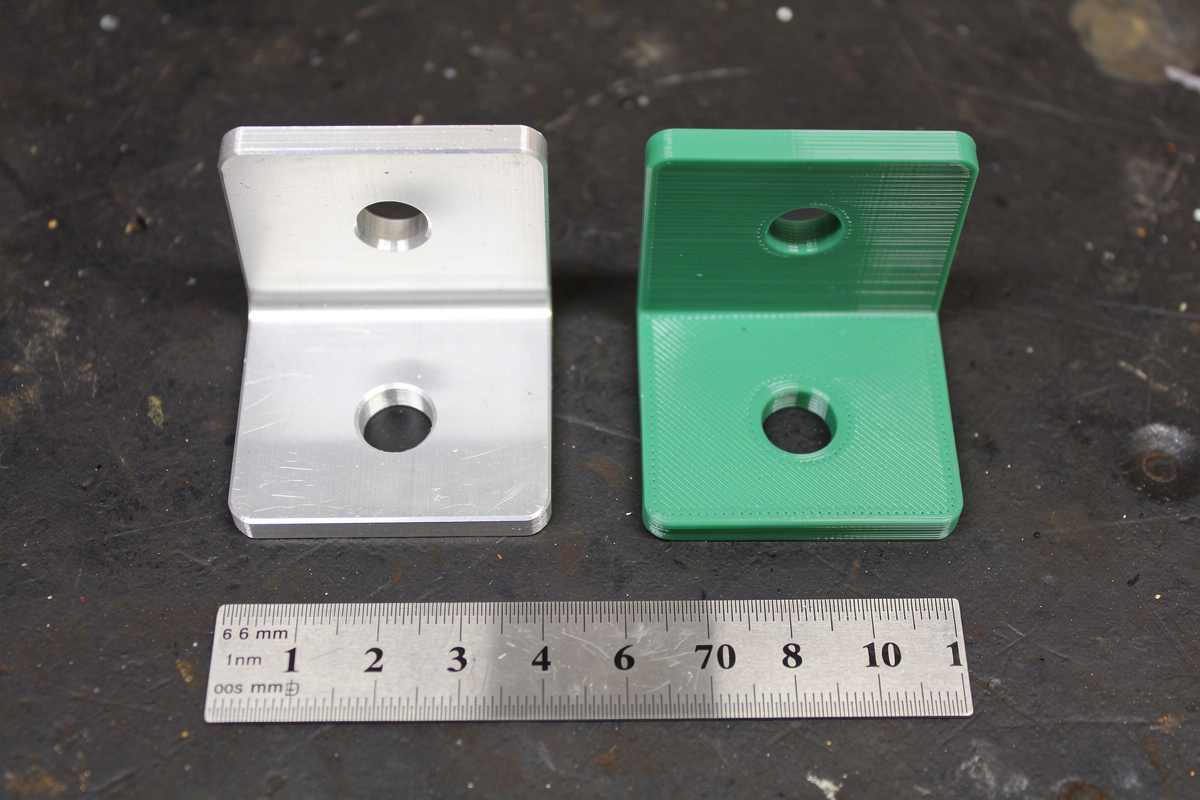
Tested on a 50mm × 25mm × 10mm bracket with a 6mm mounting hole, identical CAD model:
| Tool | Material | Density | Tensile strength | Cost |
|---|---|---|---|---|
| CNC router | 6061 aluminum | 2.70 g/cm³ | 290 MPa | $3.50 |
| CNC router | Maple hardwood | 0.71 g/cm³ | ~50 MPa parallel grain | $1.20 |
| 3D printer FDM | PLA, 50% gyroid infill | ~0.9 g/cm³ | 30–45 MPa (Z-axis 60% of XY) | $0.85 |
| 3D printer FDM | PETG, 100% solid | 1.27 g/cm³ | 40–55 MPa (Z-axis 50% of XY) | $1.40 |
| 3D printer FDM | Carbon fiber nylon (PA-CF) | 1.18 g/cm³ | 80–110 MPa | $3.20 |
| 3D printer resin | Standard resin, 100% solid | ~1.18 g/cm³ | 35–55 MPa, brittle | $2.40 |
CNC aluminum is roughly 5–10× stronger than typical FDM PLA at similar volume, and 3× stronger than carbon-fiber filled nylon. For functional parts that bear load (mounting brackets, gear teeth, structural enclosures), CNC in aluminum or hardwood is the right answer when strength is binding.
The 3D printing argument back: weight ratio. PLA at 0.9 g/cm³ is one third the weight of aluminum at the same shape. For applications where weight matters (drones, RC vehicles, handheld products), the strength-to-weight comparison tilts toward 3D printing. For applications where strength matters (machine fixtures, structural mounting), CNC wins outright. The carbon fiber filament guide covers the reinforced-filament options that close some of this gap.
Geometry: Where 3D Printing Wins
Three geometric features are essentially impossible on CNC and trivial on 3D printing:
1. Internal cavities. A hollow part with closed internal volume — for example, a fluid-routing manifold or a hollow handle with internal damping cavities. CNC can only mill from one accessible face per setup, so closed internal volumes require multi-piece assembly. 3D printing produces them in one print.
2. Overhangs and undercuts beyond simple drafts. A bracket with a hook that wraps under itself, a snap-fit clip, organic curves with negative draft. CNC can produce some undercuts with 4-axis or 5-axis setups (most desktop CNCs are 3-axis), but the toolpath complexity and clamping limitations make these expensive. 3D printing handles them via support structures.
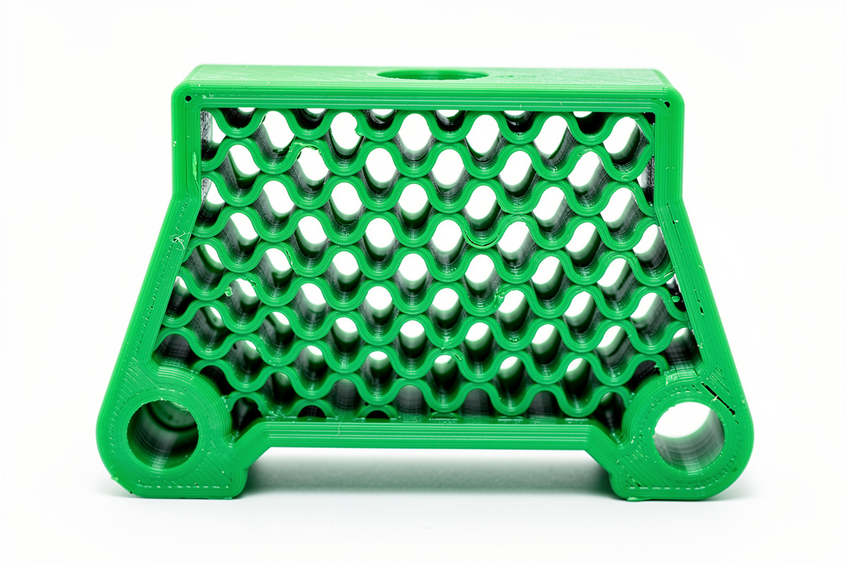
3. Lattice structures and infill patterns. A bracket with a 30% gyroid infill providing 70% of solid strength at 30% of solid weight. This is the single most useful geometry advantage of 3D printing — you can dial in the strength-to-weight curve continuously. CNC can rough out pockets but cannot produce true lattice patterns at any meaningful complexity.
For these geometries, 3D printing is not “the better choice” — it is the only choice. CNC simply cannot produce them on a 3-axis machine. The desktop CNC buyer’s guide covers what 3-axis machines can and cannot accomplish; the geometric limits are part of the buying decision.
Surface Finish: The Visual Quality Comparison
Side-by-side surface finish on the same bracket:
CNC aluminum, 1mm endmill, conventional finish pass: Visible tool marks at 0.05mm depth. Smooth to the touch but not mirror. Anodizing or polishing produces retail-quality finish.
CNC aluminum, ball endmill 3D finish pass: Cusp marks at 0.01–0.02mm. Buffs to mirror finish in 5–10 minutes. The reference standard for premium-finish parts.
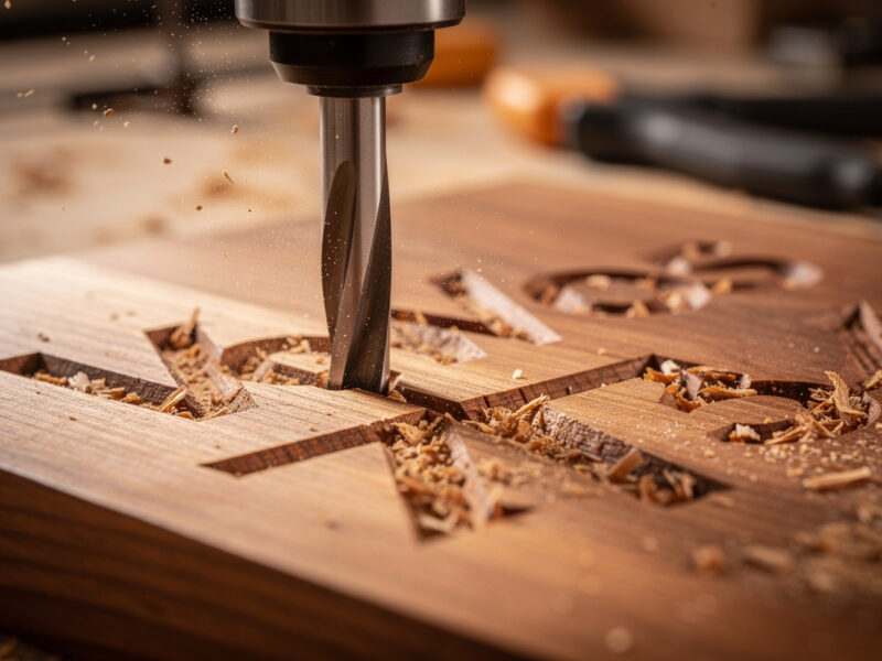
CNC hardwood, downcut finish: Glass-smooth on the top face, mild tear-out on the bottom face. With wood selection (closed-grain hardwoods like maple, cherry) and downcut bit, finish is comparable to a planer.
3D printed FDM, 0.2mm layer: Visible layer lines. Acceptable for functional parts; not for retail-quality cosmetic surfaces. 0.1mm layers reduce visibility but never eliminate.
3D printed FDM, 0.05mm layer + smoothing: Layer lines barely visible. Acetone smoothing on ABS produces near-injection-molded finish. PLA does not respond to chemical smoothing — sanding and primer fills are required.
3D printed resin, 0.05mm layer: No visible layer lines on flat faces. Stair-stepping visible on shallow angles. Post-cure required. Sanding and priming gets to retail finish in 30–60 minutes per part.
For exterior cosmetic parts (consumer products, retail goods, display models), CNC and resin printing both reach acceptable quality with finishing. FDM 3D printing requires significant post-processing to match. For internal mechanical parts where finish does not matter, all three are equivalent. The slicer software guide covers layer-height and quality settings that affect printed finish.
Time and Cost Per Part
For the test bracket (50×25×10mm with 6mm hole):
| Method | Material cost | Setup time | Run time | Total time per part |
|---|---|---|---|---|
| CNC, 6061 aluminum | $3.50 | 20 min CAM + fixture | 14 min | 34 min (one-off) |
| CNC, maple wood | $1.20 | 15 min CAM + fixture | 9 min | 24 min (one-off) |
| 3D print, PLA 50% infill | $0.85 | 5 min slice | 1h 45min unattended | 1h 50min (but unattended) |
| 3D print, PETG 100% | $1.40 | 5 min slice | 3h 20min unattended | 3h 25min |
| 3D print, resin | $2.40 | 5 min slice | 2h 40min | 2h 45min + 20min post-cure |
The pattern: 3D printing has lower attended time but higher total time. CNC has higher attended time but completes faster overall. For batch production, 3D printers run unattended overnight, which inverts the comparison — 12 parts on a printer print while you sleep, while 12 CNC parts each require attended setup.
Per-part cost favors 3D printing on small batches and one-offs (FDM PLA at $0.85 is the cheapest option). CNC favors larger batches once setup is amortized — running 50 brackets through a CNC takes 15 minutes setup + 12 minutes per part, versus 50 prints at 1h 45min each.
For functional one-offs you need today: 3D print PLA, finish in 2 hours including print. For functional batches you need next week: CNC aluminum, complete a session of 20 in 4–5 hours. For prototype-to-production iterations: 3D print first, CNC the final.
The CAM Workflow for CNC: Where Time Goes
Most “CNC is too slow” complaints come from beginners who underestimate CAM setup. A breakdown of where CAM time actually goes:
Stock definition (1–3 minutes): Tell Fusion 360 the size and origin of your raw material. Quick once you have a template.
Setup orientation (2–5 minutes): Define the work-coordinate system, fixture clearance, work-holding strategy.
Toolpath definition (5–15 minutes per pass): Roughing pass with adaptive clearing or pocket strategy, finishing pass with contour or scallop strategy. Each toolpath needs feeds, speeds, stepover, and depth-per-pass parameters. The CNC feeds and speeds chart is the reference that turns this from guesswork into engineering.
Simulation (3–5 minutes): Verify the toolpath will not crash, gouge, or leave material untouched. Worth every second.
Post-processing (1 minute): Generate G-code for your specific controller.
Total: 12–30 minutes for a moderately complex part. For repeat parts, this drops to 2–5 minutes (re-use the existing CAM setup, swap stock origin only).
The 3D roughing and finishing toolpaths article covers the strategy choices that matter most for parts with curved surfaces (which is where Fusion 360 shines compared to simpler CAM packages).
Decision Framework: When to Choose Each Path
Three questions almost always resolve the choice:
1. Does the part have features that CNC cannot make? Closed internal cavities, lattice infill, severe undercuts, organic snap-fit clips → 3D print, no CNC option.
2. Does the part need strength or stiffness CNC delivers? Load-bearing fixtures, machine mounting brackets, parts requiring metal → CNC, no 3D print equivalent without engineering compromise.
3. How many parts and on what schedule? One part urgently → 3D print. Five parts this weekend → CNC. Fifty parts this month → CNC unless geometry forbids. Five hundred parts → outsource to injection molding or production CNC.
For most prototype work, the right pattern is: 3D print first to validate fit and form, CNC the final part for production strength and finish. The 3D print costs $1–3 and 2 hours; the CNC final costs $5–15 and 30 minutes plus material setup. Together, the workflow lands a working CNC part on the third or fourth attempt instead of wasting expensive aluminum on the first.
Hybrid Production: Using Both Tools on One Project
The most interesting projects use both tools on the same final assembly:
- 3D-printed jigs for CNC operations: Print custom hold-down fixtures, stock alignment guides, drill-template bushings. CNC them in metal once the design is validated.
- CNC-machined frame, 3D-printed accessories: Aluminum machine frame from CNC for stiffness; 3D-printed cable clips, knobs, sensor mounts that bolt onto the frame.
- 3D-printed cosmetic shells, CNC-machined functional cores: Consumer-product prototype with the aesthetic body printed and the load-bearing structure machined.
Most professional product-development workflows treat both tools as equal first-class options, choosing per part rather than per project. The best CNC under $2000 buyer’s guide covers the desktop machines that pair productively with a typical FDM 3D printer.
Common Mistakes
Three mistakes account for most “I tried CNC and 3D print and got burned” complaints.
Choosing a tool by upfront cost rather than per-part economics. A $400 CNC and a $400 3D printer have similar entry-level prices but very different per-part cost curves. Make ten parts before deciding which tool feels right.
Underestimating Fusion 360 CAM learning curve. Hobby-level Fusion 360 modeling is approachable. Hobby-level CAM is genuinely harder — feeds, speeds, climb-vs-conventional cutting, stepover percentages all matter. Plan for 20–40 hours of CAM-specific learning.
Treating 3D print orientation as a free choice. Print orientation affects strength dramatically (Z-axis is typically 60–70% of XY tensile strength) and surface finish (overhangs facing up print poorly, surfaces against the build plate print poorly). Orient functional parts so loads run perpendicular to layer lines.
Can I use the same Fusion 360 model for both CNC and 3D printing?
Yes, Fusion 360 supports both pipelines from the same model. CNC requires the Manufacture workspace and CAM toolpaths exported as G-code. 3D printing requires File > Export > STL and a slicer. Most makers use the same design and pick the fabrication path per part.
Should I CNC or 3D print a functional part?
CNC if the part needs load-bearing strength or metal material. 3D print if the part has internal cavities, lattice infill, complex undercuts, or you need it within 2 hours unattended. For prototypes, 3D print first to validate fit, then CNC the final if strength matters.
What is the strongest 3D printing material compared to CNC aluminum?
Carbon-fiber-reinforced nylon (PA-CF) at 80-110 MPa is the strongest mainstream 3D printing material, roughly 30-40% the strength of 6061 aluminum at 290 MPa. For most consumer applications, this is enough. For machine-load applications (fixtures, mounts, structural parts), CNC aluminum still wins.
Is CNC machining slower than 3D printing per part?
CNC has higher attended time (CAM setup 15-30 minutes per part the first time) but faster total time once running. 3D printing has minimal attended setup (5 minutes) but multi-hour print runs. For one-off parts CNC completes in 30-60 minutes total; 3D print completes in 1.5-4 hours total but unattended.
Can a desktop CNC do everything a 3D printer can?
No. 3-axis CNC cannot make closed internal cavities, true lattice structures, or organic undercuts. These require 3D printing. CNC also cannot use thermoplastic or resin materials. The two tools are complementary; serious makers eventually own both.
Which is cheaper to operate per part?
3D printing wins on small batches (one-off parts cost $0.85-2.40 in material). CNC wins on larger batches and metal parts where 3D printing cannot compete. For 50+ identical parts, CNC’s lower per-part time after amortized setup makes it cheaper than printing them sequentially.
Related Articles
- Best Desktop CNC 2026 — machine selection
- CNC Feeds and Speeds Chart 2026 — CAM parameter reference
- 3D Roughing and Finishing Toolpaths — strategy for curved surfaces
- CNC Aluminum Feeds and Speeds — metal cutting parameters
- Best CNC Under $2000 — budget machines that pair with FDM printers