Safety first. The following information is for educational purposes. CNC machining involves high-speed rotating cutters. Always wear eye and ear protection, never leave a running machine unattended, and verify all feeds and speeds for your specific setup.
Of every upgrade I’ve bolted onto a hobby CNC, limit switches and homing give the most capability per dollar spent. A full switch kit costs less than a single decent end mill, the wiring is an afternoon’s work, and what you get back is a machine that knows where it is in space — a fixed machine-coordinate home it can find on its own at power-on, the ability to recover after a USB hiccup or a crash, and soft limits that refuse to drive the gantry into the rail when a G-code typo asks it to. On a machine I run without homing I’m forever re-zeroing by eye; on one with it dialed in, the workflow just gets quieter and more repeatable.
This is the deep dive on adding limit and homing switches to a GRBL hobby machine — what homing actually buys you, mechanical versus inductive switches, the NO-versus-NC wiring question that trips up most first installs, the exact GRBL $ settings that make it work, and how to keep electrical noise from giving you phantom triggers. If you’re still chasing missed steps and lost position, the desktop CNC troubleshooting guide pairs with this one, and homing slots neatly into the repeatable setup routine in my complete CNC workflow.
A quick note: some links below are affiliate links. Buy through one and I may earn a small commission at no extra cost to you. I only point to gear I’d actually wire onto my own machine — details on my disclaimer page.
What Homing Actually Gives You
The single biggest thing homing buys is a known machine origin. When GRBL runs a homing cycle it drives each axis toward its switch, backs off, touches again slowly, and sets that point as machine zero in machine coordinates. From then on the controller has an absolute reference frame that survives independent of wherever you set your work zero on the stock. That sounds abstract until the first time it saves you.
The recover-and-resume case is where it earns its keep. If a USB cable twitches, the sender chokes, or you have to hit feed-hold and kill power mid-job, a machine without homing has lost all sense of position — you’re starting over, often re-zeroing and re-cutting. A homed machine can re-run the homing cycle, restore machine coordinates exactly, and (with a sender that supports it) pick the job back up from a known line. I’ve rescued more than one long aluminum job this way that would otherwise have been scrap.
Then there’s repeatability across sessions. Because machine zero lands in the same physical spot every power-on, a fixture or jig bolted to the bed keeps the same machine coordinates day after day, so a saved work offset means I can drop a part into the jig tomorrow and cut without re-probing. And the quiet hero is soft limits: once GRBL knows its travel envelope, it refuses to execute any move that would exit that envelope, throwing an alarm before motion instead of grinding the gantry into the end of the rail. A mistyped coordinate or a CAM post that spat out the wrong origin gets caught on screen, not with a stalling spindle and skipped steps.
Mechanical vs Inductive Switches
There are two families worth considering for a hobby machine: mechanical lever/roller microswitches and inductive proximity sensors. Mechanical switches are the default that ships on most kits — a snap-action microswitch, often with a roller lever, that physically closes or opens when the moving axis presses it. They cost almost nothing, they’re trivial to understand, and they work. Their weaknesses are mechanical: the contacts wear, the lever can collect dust and chips that throw off the trip point, and the physical bounce of the contacts is a source of electrical noise during the touch-off.
Inductive proximity sensors have no moving parts. They sense a metal target passing within a few millimeters and switch electronically, so there’s nothing to wear, nothing for chips to jam, and the trip point is far more consistent over thousands of cycles. The common hobby-friendly type is an NPN normally-open sensor (often labeled LJ12A3-4-Z/BX), a three-wire device — brown to +12-24V, blue to ground, black as the signal — that sinks the signal line to ground when a metal target is near. The catch is that most GRBL control boards expect a switch between the input pin and ground at logic level, so you usually run the sensor at its rated voltage and either choose a board input that tolerates it or add a simple level-matching step; an NPN sensor sinking to ground maps cleanly onto an active-low GRBL input. They also need a flat metal target square to the sensor face to trigger reliably.
My take: for a budget machine that mostly cuts wood, good mechanical switches wired carefully are completely fine and the cheapest path. For a machine cutting aluminum, throwing fine conductive dust, or one where I want the most consistent homing repeatability, inductive sensors are worth the small premium. A basic CNC limit switch kit gets a mechanical install going in an afternoon, while a set of NPN inductive proximity sensors is the upgrade when wear and chip tolerance matter.
Mechanical vs Inductive at a Glance
| Switch type | Typical cost | Repeatability | Noise immunity | Chip/dust tolerance |
|---|---|---|---|---|
| Mechanical microswitch | Lowest (cents each) | Good, drifts as contacts wear | Lower — contact bounce adds noise | Low — lever jams with chips/dust |
| Inductive proximity (NPN) | Low-moderate | Excellent, electronic trip point | Higher — clean solid-state switching | High — no moving parts to foul |
NO vs NC Wiring and Why NC Wins
This is the decision that separates a reliable install from a flaky one, and most kits ship wired the worse way. A switch can be wired normally-open (NO) — the circuit is open until the switch trips and closes it — or normally-closed (NC), where the circuit is held closed and the switch opens it on trip. Functionally GRBL can be told to expect either with the invert mask, so it seems like a wash. It isn’t.
With NO wiring, a broken wire, a loose crimp, or a connector that’s worked loose looks identical to “switch not triggered” — the input just sits there reading open, and the machine will happily drive the axis past where the switch should have stopped it, because as far as it knows nothing’s wrong. With NC wiring, the circuit is normally held closed, so a broken wire or bad connection opens the circuit and reads exactly like a triggered switch — the machine faults safely instead of running off the end. The fault mode points toward safety rather than away from it. This matters even more when you wire several switches per axis: NC switches go in series (any one opening trips the axis) and a break anywhere in the chain trips safely, whereas NO switches wire in parallel and a break silently disables a switch. I wire NC wherever the switch supports it, and inductive sensors are available in NC variants for the same reason.
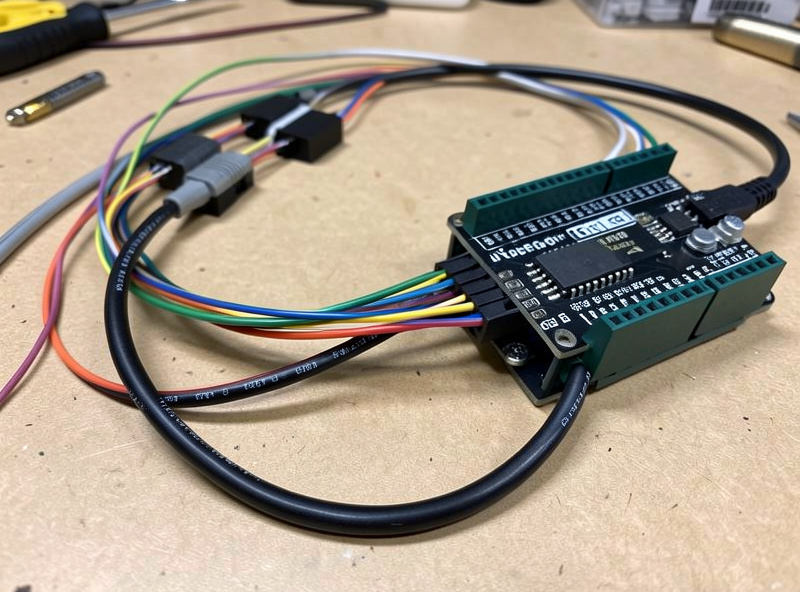
The GRBL Settings That Make It Work
This is where a wrong number is a competence tell, so get these exactly right. GRBL exposes the homing and limits behavior through its $ settings, and you set each by typing the assignment into your sender’s console. The core block:
$22=1— homing enable. This is the master switch. With$22=0there is no homing cycle at all; set it to 1 to enable the cycle and unlock homing.$21=1— hard limits enable. With hard limits on, GRBL triggers an immediate alarm the instant any limit switch is hit during normal motion. Useful, but it depends on clean wiring — noisy switches with hard limits on will give you nuisance alarms, which is why noise immunity matters.$20=1— soft limits enable. This is the one I’d never run without once homing works. Soft limits use the known travel envelope to reject any move that would leave it, faulting before motion. Soft limits require homing to be enabled and the machine to have been homed, because they need a valid machine origin to measure against.$23— homing direction invert mask. This sets which corner the machine homes toward. The bitmask flips the homing direction per axis (bit 0 = X, bit 1 = Y, bit 2 = Z); for example$23=3inverts X and Y. Get this wrong and an axis drives away from its switch into the hard stop, so this is the setting to test first with a hand on the power.$27— homing pull-off, in mm. After touching the switch, GRBL backs off this distance so the switch releases and isn’t sitting right at its trip point. I run$27=2.000or a bit more — enough to clearly clear the switch, which also stops a limit switch that doubles as a hard limit from instantly re-alarming after homing.$130,$131,$132— max travel per axis (X, Y, Z) in mm. These define the working envelope soft limits enforce. Set them to your machine’s actual usable travel — measure it, don’t guess — because too large lets the gantry crash before soft limits catch it, and too small steals working area.
Two more worth knowing: $24 is the slow homing feed (the precise second touch) and $25 the fast homing seek (the initial fast approach), and $5 is the limit-pin invert that you flip to match NC versus NO wiring so a closed NC circuit reads as “not triggered.” Always confirm with $$ to dump the full settings table after changes, and verify direction at low speed before trusting a full-rate homing seek. If you want the broader picture of how the controller’s motion settings interact, the feeds and speeds reference covers the acceleration and rate side, and the tooling fundamentals guide rounds out the rest of the setup.
Switch Placement and Mounting
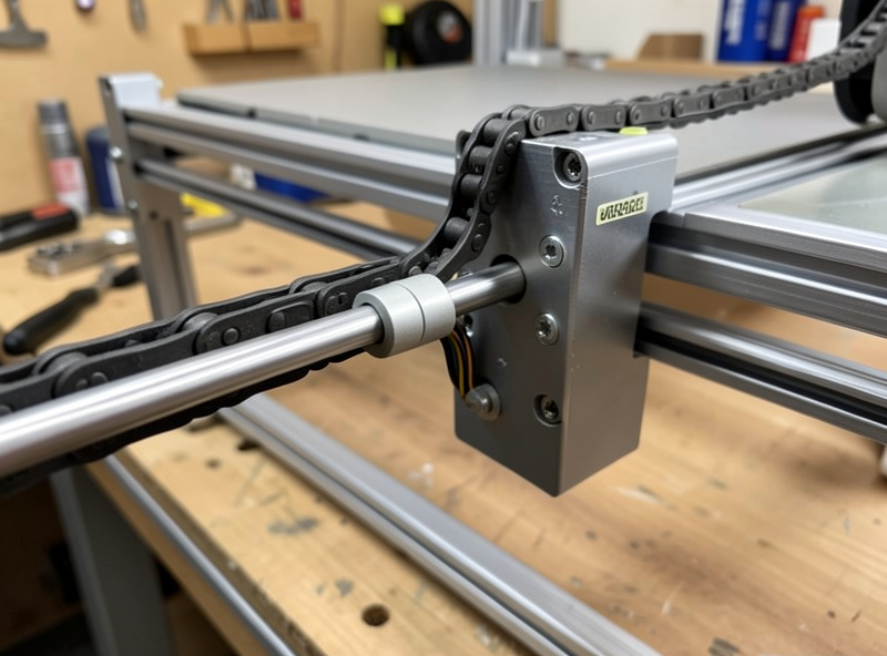
Where you mount the switch decides how repeatable homing is. The switch needs to trip at the same physical point every cycle, so it has to be rigidly mounted — a switch on a flexy 3D-printed bracket that deflects a little differently each touch will give you a homing position that wanders by tenths of a millimeter. I bolt switches to the frame or to a stout printed bracket with a metal backing, and I put them at the extreme of travel in the direction the machine homes, just clear of the hard end-stop so the axis touches the switch before it touches metal.
For mechanical switches, a roller-lever type tolerates a little misalignment better than a plain button, and I mount so the moving axis hits the lever square, not at an angle that side-loads it. For inductive sensors, the metal target needs to be flat, square to the sensor face, and within the sensing distance (typically around 4mm for an LJ12A3-4) with a small consistent gap — too far and it won’t trip, touching and it can get knocked out of alignment. On the Z axis especially, mount so a dropped Z homes up to a top switch where possible, so a homing fault doesn’t drive the spindle down into the bed.
Debouncing and Killing Electrical Noise
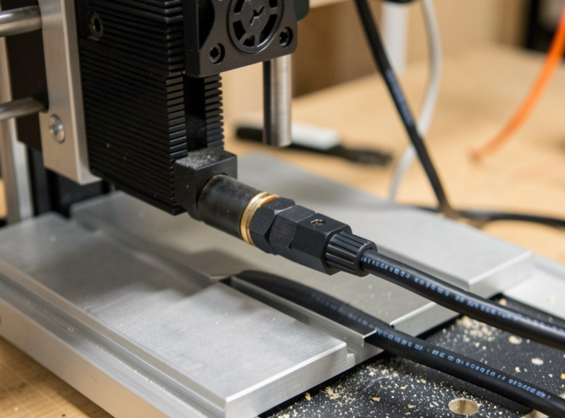
The most common reason a freshly wired homing setup throws random alarms isn’t a bad switch — it’s electrical noise. Stepper motors and a VFD spindle dump a lot of electrical hash, and a long unshielded switch wire run alongside motor cables acts like an antenna, picking up enough noise to false-trigger a limit input mid-cut. The fixes, in order of how much they help: run the switch wiring in shielded cable with the shield grounded at one end only, keep switch wires away from and crossing perpendicular to stepper and spindle cables rather than running parallel, and add a small filter capacitor (roughly 0.1µF, or 100nF, across the input to ground) to debounce the line.
NC wiring helps here too, because a momentary noise spike that briefly opens an already-open NO line does nothing, whereas the held-closed NC line is more about wiring integrity — pair NC switches with shielding and a debounce cap and false triggers largely disappear. Mechanical switches add their own contact-bounce noise on each physical touch, which is part of why I favor inductive sensors plus shielding on a noisy machine. A run of proper shielded signal wire is cheap insurance and the difference between homing that just works and a machine that alarms every third job. If you’re still fighting phantom alarms after shielding, the troubleshooting guide walks the rest of the noise diagnostics, and good cable management belongs in a tidy, safe shop — see the safe workshop setup.
Why It’s the Best Cheap Upgrade
Add up what a switch kit and a length of shielded wire cost against what they return — a machine that finds its own home, recovers from crashes, holds repeatable fixtures, and refuses to grind itself into the rail — and nothing else on the upgrade list comes close on value. It’s the upgrade I’d do before a better spindle, before fancier bits, before almost anything, because it changes the whole tenor of how the machine runs. If you’re shopping a new machine, homing-ready electronics are worth checking for; my picks in the best desktop CNC roundup and the Shapeoko 5 Pro review note which arrive with switches already wired, and the Fusion 360 for hobby CNC guide shows how a known machine origin tightens up the whole CAM-to-cut loop.
Frequently Asked Questions
Do I really need limit switches on a hobby CNC?
You can run without them, but homing gives a known machine origin at power-on, lets you recover after a crash or USB drop, keeps fixtures repeatable across sessions, and enables soft limits that stop a G-code typo from driving the gantry into the rail. For the cost of a switch kit it is the highest-value upgrade most hobby machines can get.
Should I wire limit switches normally-open or normally-closed?
Normally-closed is safer. With NC wiring a broken wire or loose connector opens the circuit and reads like a triggered switch, so the machine faults safely. With normally-open wiring the same fault looks identical to a switch that simply has not tripped, so the machine keeps moving. Wire NC wherever the switch supports it.
Which GRBL settings enable homing and soft limits?
Set 22 to 1 to enable homing, 20 to 1 for soft limits, and 21 to 1 for hard limits. The 23 mask sets homing direction per axis, 27 sets the pull-off distance in mm after touching the switch, and 130, 131, and 132 set max travel per axis so soft limits know the envelope. Soft limits require homing to be enabled and the machine to have been homed.
What is the difference between mechanical and inductive limit switches?
Mechanical microswitches are cheapest and trip when the axis physically presses a lever, but the contacts wear and chips can jam them. Inductive proximity sensors have no moving parts, sense a metal target electronically, and offer better repeatability and chip tolerance for a small premium. Mechanical is fine for wood machines; inductive suits aluminum and dusty shops.
Why do my limit switches trigger false alarms during a cut?
Almost always electrical noise from stepper motors or a VFD spindle coupling into the switch wiring. Run the switch wires in shielded cable grounded at one end, keep them away from and crossing perpendicular to motor cables, add a small debounce capacitor across the input, and prefer NC wiring. That combination eliminates most phantom triggers.