Safety first. The following information is for educational purposes. CNC machining involves high-speed rotating cutters. Always wear eye and ear protection, never leave a running machine unattended, and verify all feeds and speeds for your specific setup.
GRBL setup is a six-step sequence: install the USB driver and a sender, connect at 115200 baud, fix any backwards axis with the invert masks, calibrate steps-per-mm, set travel and acceleration, then enable homing and save. Done in order, a blank board is cutting accurately in under an hour. Done out of order, you chase ghosts for a week.
I have set up GRBL from scratch on every machine on my bench — the Genmitsu PROVerXL and 3018-PROVer, and a couple of board swaps on the Shapeoko. The process is the same every time, and the order matters more than any single value. This guide walks the exact sequence I use, with the settings that actually decide whether the machine cuts true. It is the hands-on companion to my CNC control software guide, which maps how firmware, senders, and settings fit together.
What GRBL Needs Before You Start
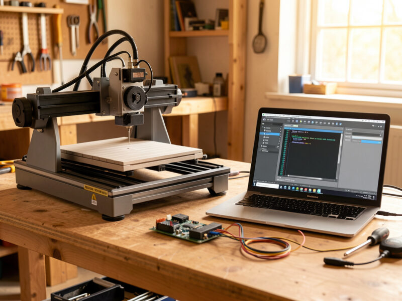
GRBL is the firmware already burned onto your controller board. To talk to it you need three things on your computer: the USB-serial driver, a G-code sender, and the right baud rate. Miss any one and the board simply will not connect, which is the single most common first-day frustration.
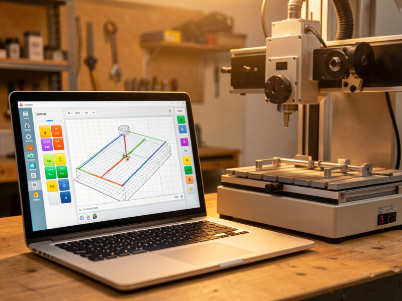
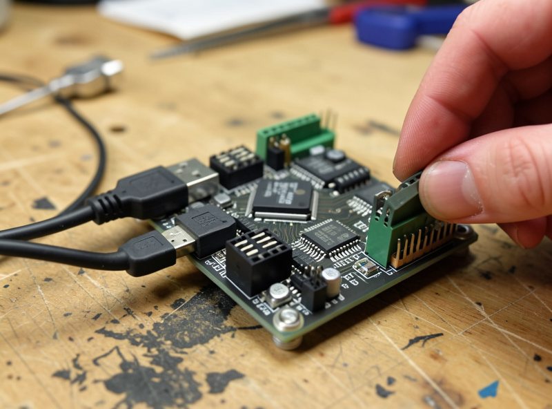
Most GRBL boards use a CH340 or FTDI USB chip. On Windows the CH340 driver is the first install — without it the board never shows up as a COM port. For the sender, I default to gSender from Sienci Labs because it is free and its setup wizard is forgiving; UGS works too if you want something cross-platform. GRBL communicates at 115200 baud by default, so set your sender to that. If your console fills with garbage symbols, that is a baud mismatch, not a broken board. Choosing between senders is its own decision — I break it down in gSender vs UGS vs Carbide Motion.
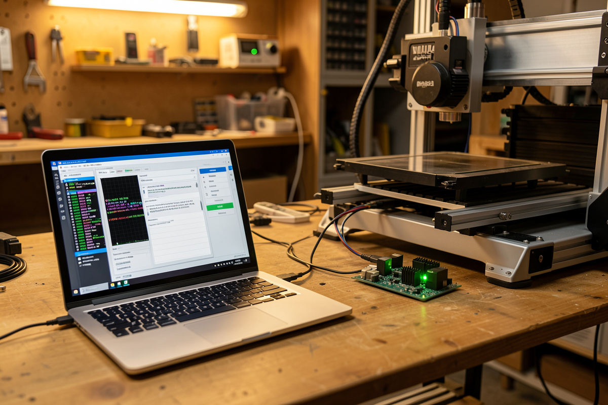
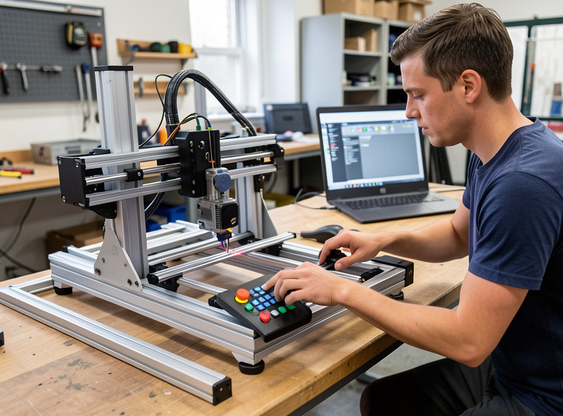
Step 1: Connect and Read the Firmware
With the driver installed and the sender open, select the COM port and connect. GRBL greets you with a startup line like Grbl 1.1h ['$' for help]. Seeing that line is the whole goal of step one — it means firmware, USB, and sender are all talking.
Now type $I to read the firmware version and build, and $$ to dump the full settings list — about 35 numbered parameters. Before you change anything, copy that entire $$ output into a text file and save it. This is your factory baseline; if you ever fat-finger a setting or flash new firmware, you paste it back instead of rebuilding from scratch. I keep a dated config file for every machine on the bench, and it has saved me hours after a board swap. Knowing your version matters because GRBL 1.1 added settings that 0.9 does not have, and senders expect 1.1.
Step 2: Fix Motor Direction and Step Signal
Before anything else moves under a real cut, confirm each axis jogs the correct way. Jog X positive — the gantry (or tool) should move right. Jog Y positive — it should move toward the back. Jog Z positive — the tool should move up, away from the work. A backwards axis is dangerous because homing will then drive into the wrong end and crash.
You fix a reversed axis in software, not by rewiring. The $3 direction-invert mask flips axes: $3=1 inverts X, $3=2 inverts Y, $3=4 inverts Z, and you add the numbers to invert combinations ($3=3 flips X and Y). If a motor moves the wrong way, change $3 rather than swapping motor wires — it is faster and reversible. While you are here, leave $0 (step pulse) and $1 (step idle delay) at their defaults unless your drivers specifically need more; $1=255 keeps the steppers energized so the axis holds position, which I prefer on a router.
Step 3: Calibrate Steps-Per-Mm
Steps-per-mm ($100 for X, $101 for Y, $102 for Z) is the number that controls dimensional accuracy — how many motor steps equal one millimeter of travel. A factory default gets you close, but mechanical reality means it is rarely exact, and a 2% error shows up as undersized parts.
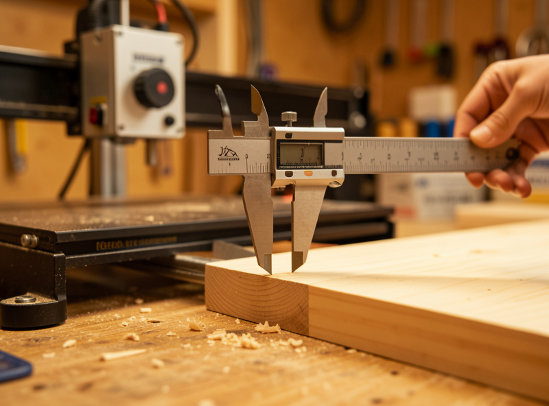
Calibrate with a measure-and-correct loop. Command a known move — I use 100 mm because the math is clean — then measure the actual travel with calipers or a steel rule against a fixed point. The new value is new = (current_steps × commanded) / actual. So if $100 is 200 and a commanded 100 mm actually moves 98.5 mm, the corrected value is (200 × 100) / 98.5 = 203.05. Set it with $100=203.05 and re-test. Do all three axes. This five-minute loop is why my parts come off the machine the size the CAD said, and it is the fix for the most common “everything is slightly small” complaint. The deeper theory behind every parameter is in tuning GRBL $ settings.
Step 4: Set Max Rate and Acceleration Safely
Max rate ($110/$111/$112, in mm/min) caps how fast each axis can travel; acceleration ($120/$121/$122, in mm/sec²) sets how hard it ramps up to that speed. These two settings cause more lost steps than anything else, because asking a hobby gantry to accelerate harder than its mass and motors allow makes the steppers skip — and a skipped step means every coordinate after it is wrong.
Set these conservatively. Start with the manufacturer’s stock values, then if you want more speed, raise $120 in steps of 25–50 and run a rapid back and forth across the full axis. The moment you hear a stall or grinding, back off 20% and leave margin. I keep acceleration deliberately below the cliff because a slightly slower rapid is invisible in a finished part, but a lost step ruins the whole job. Z almost always needs lower acceleration than X and Y because it fights gravity and the leadscrew. This is rigidity tax in software form: a flexier machine has to be told to move gentler.
Step 5: Set Travel, Then Enable Homing and Soft Limits
The travel settings ($130/$131/$132) tell GRBL how far each axis can physically move. Set them to your machine’s real working envelope, slightly under the absolute mechanical limit. These numbers are meaningless on their own — but they are what makes soft limits possible, so they come before homing.
If your machine has limit switches, enable homing with $22=1, then set the seek and feed speeds ($25 and $24) and the pull-off distance ($27, usually 1–3 mm so the switch releases after triggering). Use $23 to set which corner the machine homes to. Once homing is reliable — it returns to the same spot twice in a row — turn on soft limits with $20=1, and GRBL will refuse a job that would exceed your $130-$132 envelope instead of crashing the gantry. The full homing walkthrough, including the $5 limit-pin invert mask for switches that read backwards, is in CNC homing and limit switch setup.
Step 6: Save and Back Up Your Configuration
GRBL settings write to the board’s EEPROM the moment you enter them, so there is no separate save button — but you still need a backup. Type $$ again, copy the now-tuned output, and save it as a dated config file alongside your factory baseline.
Here are the essential first-setup values worth recording, with what each controls:
| Setting | Controls | Set when |
|---|---|---|
| $3 | Axis direction invert | An axis jogs backwards |
| $100 / $101 / $102 | Steps-per-mm (accuracy) | Parts come out wrong size |
| $110 / $111 / $112 | Max travel rate | Tuning rapid speed |
| $120 / $121 / $122 | Acceleration | Losing steps under hard moves |
| $130 / $131 / $132 | Max travel envelope | Before enabling soft limits |
| $22 / $20 | Homing / soft limits | Machine has limit switches |
That backup is worth the thirty seconds. The next time you change firmware — a topic I cover in the flashing CNC firmware guide — a flash wipes EEPROM to defaults, and pasting your saved block back is the difference between a five-minute recovery and a full re-calibration.
Common First-Setup Mistakes
The board will not connect: nine times out of ten it is a missing CH340 driver or the wrong COM port, not a dead board. Garbage in the console is a baud rate that is not 115200. An axis crashes into the frame on homing: a direction or homing-direction mask is wrong — fix $3 and $23 before homing again. Parts are consistently undersized: steps-per-mm needs calibrating. The machine stalls on fast moves: acceleration is too high for the gantry.
None of these are hardware faults, and that is the point — almost every first-day problem lives in the settings, which is exactly why getting them right in order saves so much grief. When a fault is genuinely mechanical, my troubleshooting desktop CNC guide separates the control-layer causes from the rigidity ones. If you are setting up an inexpensive first machine, the Genmitsu 3018 review covers the quirks of that specific GRBL board.
Frequently Asked Questions
How do I open the GRBL settings?
Connect your sender to the board at 115200 baud, then type $$ in the console. GRBL prints its full list of about 35 numbered settings. Type $I to see the firmware version. Save that output to a text file before changing anything.
Why won’t my GRBL board connect to my computer?
On Windows it is almost always a missing CH340 USB driver or the wrong COM port selected. Install the CH340 driver, pick the correct port, and set the baud rate to 115200. A board that worked before rarely dies on its own.
How do I fix an axis that moves the wrong way in GRBL?
Use the $3 direction-invert mask instead of rewiring. $3=1 inverts X, $3=2 inverts Y, $3=4 inverts Z, and you add the numbers for combinations. Fix this before enabling homing, or the machine will drive into the wrong end and crash.
What is the correct steps-per-mm value for my machine?
There is no universal value; it depends on your motors, drivers, and drive mechanism. Calibrate it: command a 100 mm move, measure the actual travel, and set new = (current x 100) / measured. Do this for $100, $101, and $102 separately.
Do GRBL settings save automatically?
Yes. Each $ setting writes to the board’s EEPROM the instant you enter it, so there is no save button. But you should still copy the full $$ output to a text file as a backup, because flashing firmware resets EEPROM to defaults.
Why does my machine lose steps on fast moves?
Acceleration ($120, $121, $122) is set too high for your gantry’s mass and motors, so the steppers skip. Lower the value by 20 percent and re-test with a full-speed rapid. Z usually needs lower acceleration than X and Y because it fights gravity.
Related Guides
- CNC Control Software Guide — how firmware, senders, and settings fit together
- Tuning GRBL $ Settings — every parameter explained
- CNC Homing and Limit Switch Setup — enabling homing the right way
- Flashing CNC Firmware Guide — when EEPROM gets wiped
- Squaring and Calibrating Your CNC Router — accuracy beyond steps-per-mm